1 stepper motor control systems (pulse/direction), 4function description, 3 control element – Pilz PMCtendo DD5.03/000/0/0/0/110-230VAC User Manual
Page 56
4.3
Control element
4
Function description
Pilz GmbH & Co. KG, Felix-Wankel-Straße 2, 73760 Ostfildern, Germany
Telephone: +49 711 3409-0, Telefax: +49 711 3409-133, E-Mail: [email protected]
4-28
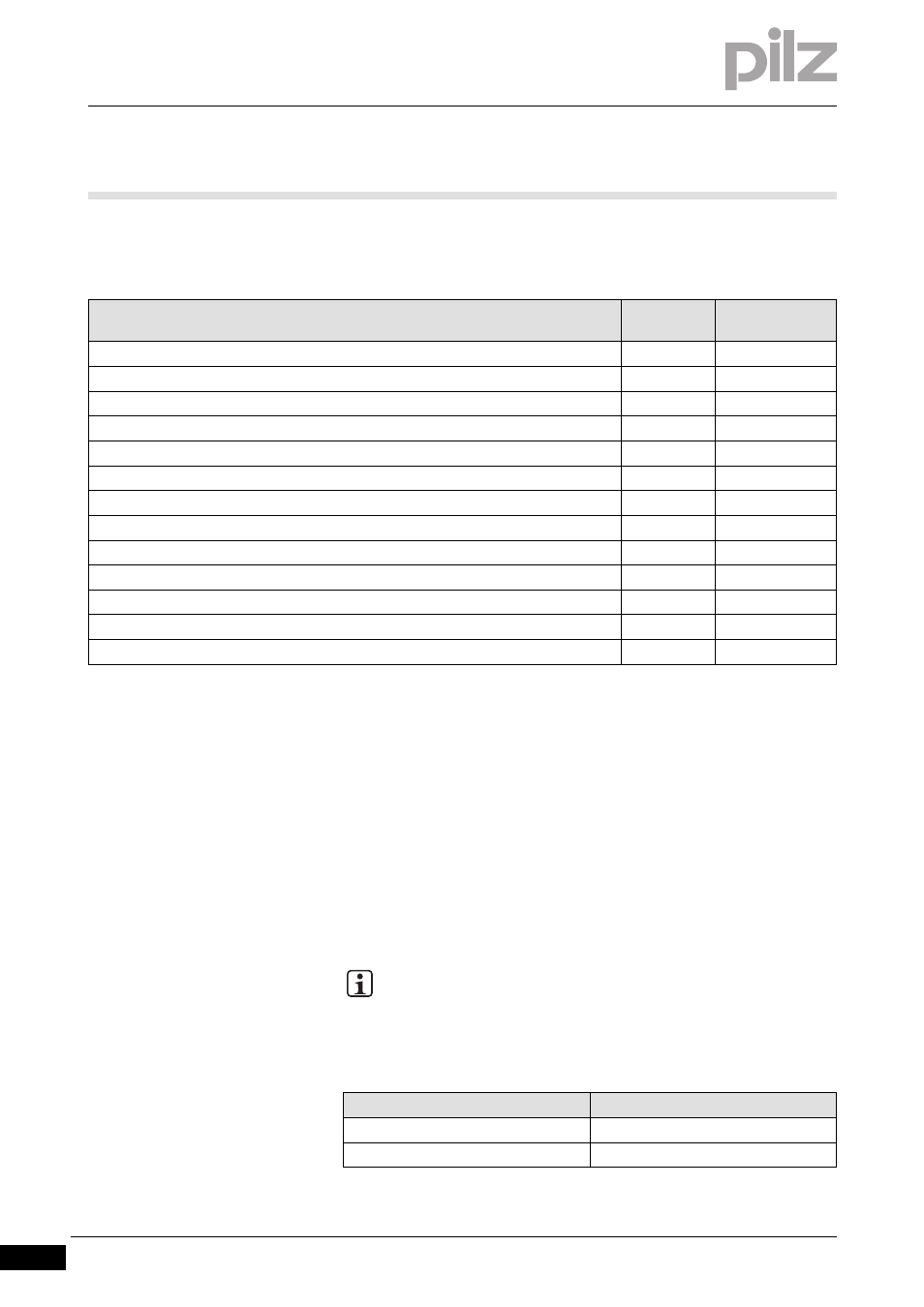
The following types may be used as external encoders for the reference
signal:
4.3.6.1
Stepper motor control systems (pulse/direction)
Stepper motor control systems (pulse/direction)
4-
][Funktion_Schrittmotorsteuerung
Functions:
You can connect the servo amplifier to a vendor-neutral stepper mo-
tor control system.
Signal level 5 V or 24 V
Parameters for the servo amplifier are set using the commissioning
software (electronic gearing). The number of steps is selectable. As a
result, the servo amplifier can be adapted to the pulse/direction sig-
nals of any stepper motor control system.
Parameter setting:
Encoder type
Connector
Parameter
GEARMODE
SinCos encoder with BiSS digital interface
X1
11, 12
SinCos encoder with EnDat 2.1 interface
X1
8
SinCos encoder with EnDat 2.2 interface
X1
13
SinCos encoder with HIPERFACE interface
X1
9
SinCos encoder without data track
X1
6, 7
Incremental encoder (AquadB) 5 V, 350 kHz
X1
10
Incremental encoder (AquadB) 5 V, 1.5 MHz
X1
30
Incremental encoder (AquadB) 5 V, 1.5 MHz
X5
3
Absolute encoder with SSI interface 5 V
X1
25
Absolute encoder with SSI interface 5 V
X5
5
Pulse/direction 5 V
X1
27
Pulse/direction 24 V
X3
1
Pulse/direction 5 V
X5
4
INFORMATION
Use an incremental encoder to achieve higher EMC immunity.
Control
Parameter GEARMODE
Pulse/direction 5 V (X1)
27
Pulse/direction 24 V (X3)
1