13 encoder emulation, 6wiring, 7 control element – Pilz PMCtendo DD5.03/000/0/0/0/110-230VAC User Manual
Page 144
6.7
Control element
6
Wiring
Pilz GmbH & Co. KG, Felix-Wankel-Straße 2, 73760 Ostfildern, Germany
Telephone: +49 711 3409-0, Telefax: +49 711 3409-133, E-Mail: [email protected]
6-54
6.7.5.13
Encoder emulation
Encoder emulation
6-
][Verdr_Emulation_ROD_protego_D
Output of incremental encoder signals
][Verdr_Emulation_SSI_protego_D
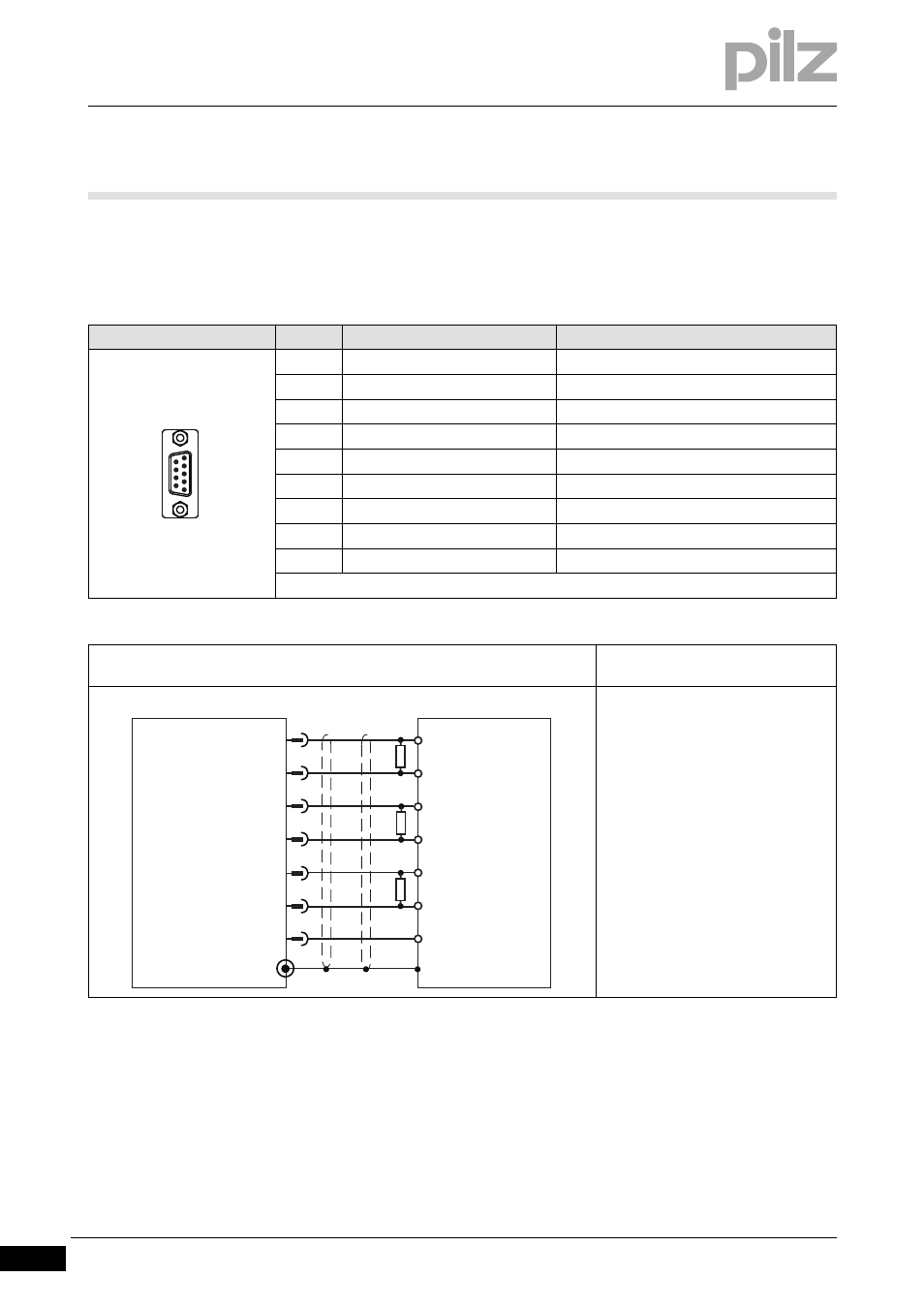
Connector pin assignment
Connector X5
Pin
Designation
Description
1
GND
Earth
2
NI
Zero
p
ulse
3
NI\
Zero impulse inverted
4
A\
Channel A inverted
5
A
Channel A
6
B
Channel B
7
B\
Channel
B
inverted
8
n. c.
--
9
n. c.
--
n. c. = not connected
Connection
Output circuit
Output of incremental encoder sig-
nals
Shield connection in the connector
Always connect GND to the earth on
the control system
Select R
T
in accordance with the ca-
ble impedance, typically 150
Ω
Max. cable length: 100 m
1
5
6
9
5
4
6
Servo Drive
X5
2
PLC
7
3
B
B\
A
A\
NI
NI\
GND
1
B
B\
A
A\
NI
NI\
GND
RT
RT
RT