Messages/errors, 1 status messages, 2 error messages – Pilz PMCtendo DD5.03/000/0/0/0/110-230VAC User Manual
Page 169: 7commissioning, 4 messages/errors
Pilz GmbH & Co. KG, Felix-Wankel-Straße 2, 73760 Ostfildern, Germany
Telephone: +49 711 3409-0, Telefax: +49 711 3409-133, E-Mail: [email protected]
7-13
7.4
Messages/errors
7
Commissioning
7.4
Messages/errors
7400
Messages/errors
7-
7.4.1
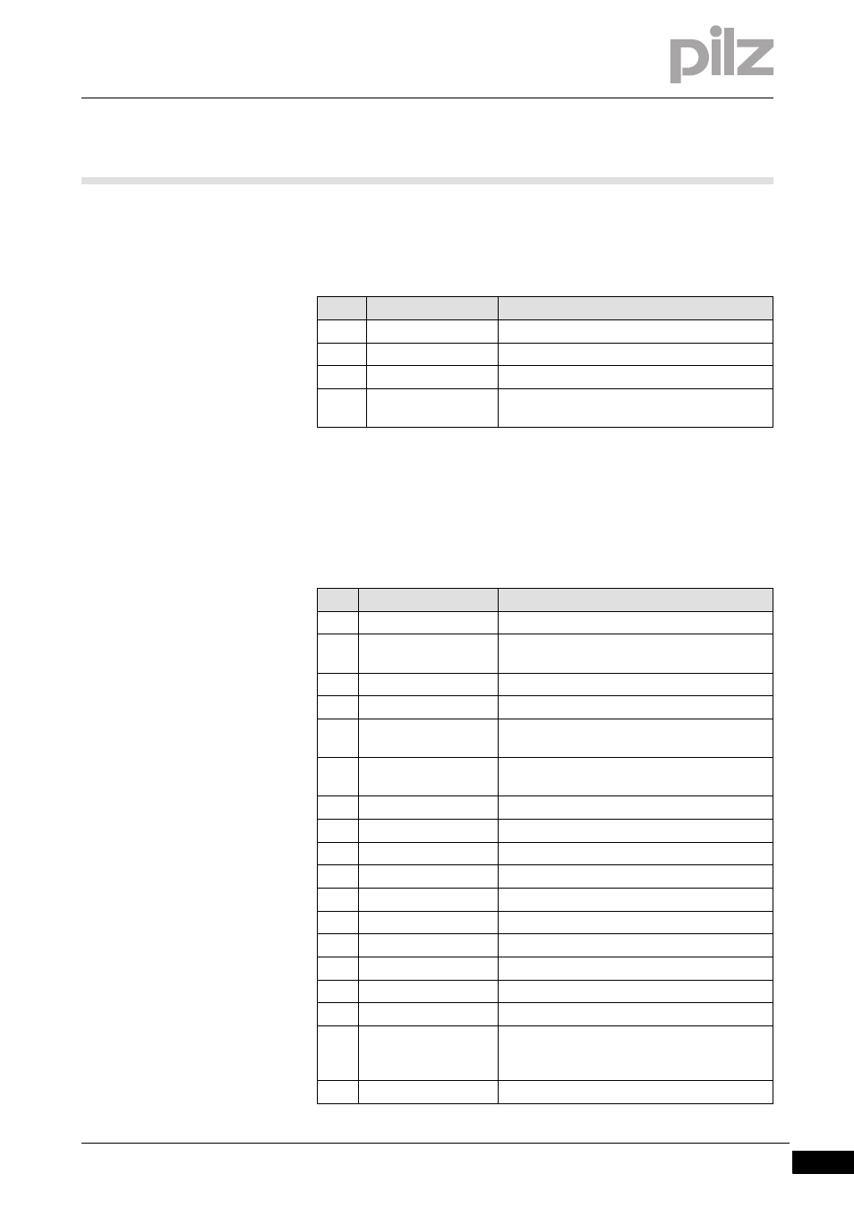
Status messages
Status messages
7-
][Inbetrieb_Meldung_Status_DD5
Status messages on the LED display indicate the operating status of the
servo amplifier.
7.4.2
Error messages
Error messages
7-
][Inbetrieb_Meldung_Fehler_DD5
Error are shown on the LED display with an error number. If an error oc-
curs, the BTB contact opens. The output stage of the servo amplifier
shuts down (motor is torque-free). The motor holding brake is activated.
No.
Error message
Description
E//P
Status messages
Status message, no error
. . .
Status message
Amplifier updating the start configuration
-
Status message
Status message, no error, programming mode
- S -
STO-ENABLE
STO-ENABLE input = 0 V (if the drive is shut
down)
No.
Error message
Description
F01
Heatsink temperature
Heatsink temperature too high (default: 80?)
F02
Overvoltage
Overvoltage in the intermediate circuit. Limit
value depends on the mains voltage
F03
Drag error
Message from the position controller
F04
Feedback
Open circuit, short circuit, earth fault
F05
Undervoltage
Undervoltage in the intermediate circuit (de-
fault: 100 V)
F06
Motor temperature
Temperature sensor defective or motor tem-
perature too high
F07
Internal voltage
Internal supply voltages faulty
F08
Overspeed
Motor runs away, speed higher than permitted
F09
EEPROM
Check sum error
F10
Reserved
Reserved
F11
Motor brake
Open circuit, short circuit, earth fault
F12
Motor phase
Motor phase missing (open circuit or similar)
F13
Ambient temperature
Ambient temperature too high
F14
Output stage
Fault in the power output stage
F15
I²t max.
I²t maximum value exceeded
F16
Mains BTB
2 or 3 infeed phases missing
F17
A/D Converter
Error in the analogue/digital conversion, often
caused by very strong electromagnetic inter-
ference
F18
Brake chopper
Brake circuit defective or incorrect setting