Elecraft K2 Owner's Manual User Manual
Page 9
8
E
LECRAFT
®
Board-to-board Connectors
The circuit boards in the K2 are interconnected using board-to-board
connectors, which eliminates nearly all hand wiring. Gold-plated
contacts are used on these connectors for reliability and corrosion
resistance.
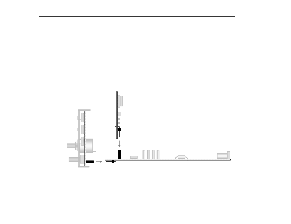
Figure 3-3 shows a side view of the PC boards and board-to-board
connectors. As can be seen in the drawing, the Front Panel board has a
connector J1 which mates with right-angle connector P1 on the RF
board. Similarly, right-angle connector P1 on the Control Board mates
with J6 on the RF board. (Not shown in this drawing are two
additional right-angle connectors on the Control board, P2 and P3,
which mate with J7 and J8 on the RF board.)
These multi-pin connectors are very difficult to remove once
soldered in place. Refer to Figure 3-3 during assembly to make
sure you have each connector placed correctly before soldering.
J1
P1
J6
P1
Front Panel
RF Board
Control Board
Figure 3-3
- KX3 Owner's Manual (58 pages)
- KX3 Assembly Manual (47 pages)
- KX3 Assembly Manual Errata (5 pages)
- KX3-2M (30 pages)
- KX3-PCKT (2 pages)
- KX3 Mobile Installation And Operation Guide (17 pages)
- KX3 Guide for Blind Operators (7 pages)
- KX3 Quick Reference (2 pages)
- K3 Programmers Reference (26 pages)
- KX3 Speaker Grille Instructions (9 pages)
- KXFL3 Filter Option (12 pages)
- KXFL3 Filter Option Errata (2 pages)
- KXAT3 (5 pages)
- KXBC3 (13 pages)
- KXPD3 (4 pages)
- Proset Boom Headset (1 page)
- PX3 Owner's Manual (53 pages)
- PX3 Owners Manual Errata (2 pages)
- KXPA100 Manual (55 pages)
- KXPA100 Assembly Manual (27 pages)
- KXPA100 Assembly Errata (1 page)
- KXPA100 Programmers Reference (24 pages)
- KXAT100 Installation Manual (17 pages)
- KX1 Manual (96 pages)
- KXAT1 (12 pages)
- KXPD1 (7 pages)
- KXB30 (8 pages)
- KXB3080 (20 pages)
- K1 (91 pages)
- K1 1.09 F/W (1 page)
- KNB1 Manual (8 pages)
- KAT1 Manual (15 pages)
- KFL1-2 (2 pages)
- KTS1 (1 page)
- KBT1 Manual (8 pages)
- KBT1 Manual Errata (2 pages)
- K1BKLTKT LCD Mod Kit (6 pages)
- K2 Owner's Manual Errata (1 page)
- K2 PLL (4 pages)
- K2ATOBKIT (15 pages)
- K2ATOBKT (2 pages)
- K2 Keying Modification Instructions (4 pages)
- KPA100 Manual (74 pages)
- KPA100 Shield Upgrade (3 pages)