Elecraft K2 Owner's Manual User Manual
Page 63
62
E
LECRAFT
®
Resistance Checks
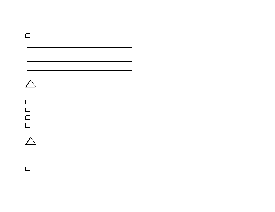
Perform the following resistance checks:
Test Point
Signal Name
Res. (to GND)
R115, right end (near S1)
12V IN
> 500 ohms
U6 pin 8
8B
> 100 ohms
U4 pin 16
5B
> 1 k
U11 pin 8
8A
> 250 ohms
U10 pin 8
8T
> 500 ohms
U12 pin 1
8R
> 500 ohms
i
It's very important to re-assemble the chassis as described
below before attempting the alignment steps in the next section. If you
don’t put the chassis together, some results will not be accurate.
Install the side panels and secure with two chassis screws each.
Plug in the front panel assembly. Secure with two chassis screws.
Plug in the Control board.
Secure the front panel and Control boards together using two
chassis screws.
i
Before installing the bottom cove in the next step, verify that
all components on the bottom of the RF board have an installed height
of 1/4" (6 mm) or less. Capacitors or other parts that stand above this
height must be bent downward at an angle to prevent them from
hitting the bottom cover.
Install the bottom cover and secure it temporarily using six
chassis screws.