Signal tracing – Elecraft K2 Owner's Manual User Manual
Page 161
9
Signal Tracing
Signal tracing is the primary method by which radio equipment is tested and
repaired. You can solve nearly all receiver and transmitter problems yourself
by following the steps in this section carefully.
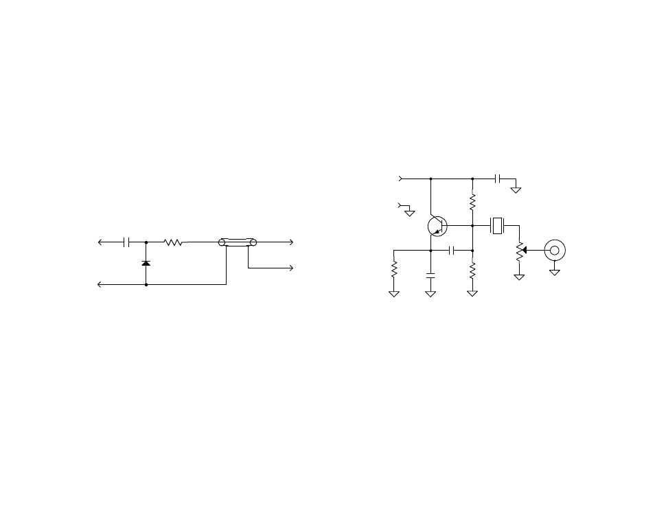
RF Probe Assembly
Your K2 kit includes a complete RF probe, including the PC board, coax,
and connectors. The switch spacing tool, which you used in assembling the
Front Panel, doubles as the PC board for the probe. The RF probe (Figure
1) converts RF signals to DC so they can be measured using a DMM. The DC
readings on your DMM will be approximately equal to the signal voltage in
Vrms (root-mean-square).
.01µF
1N34A
probe
4.7Mohm
C1
D1
R1
E1
tip
24" (60 cm)
To DMM
E2
ground
COAX,
P1
P2
(+)
(-)
Figure 1
Assembly Instructions: Use a discarded lead from a large diode such as an
SB530 or 95SQ015 as the probe tip (E1). It should be about 1" (2.5 cm) long.
All other components for the probe can be found in the MISCELLANEOUS
bag. An insulated alligator clip is provided for ground (E2). It should be
connected to the board using 4" of black insulated hookup wire. Two banana
plugs are supplied for connecting the probe to your DMM (P1-P2). Use
RG174 coax between the probe board and the banana plugs. The coax should
be secured to the board using one cable tie. Thread the cable tie through the
two holes provided, near the coax end of the board.
To use the Probe: Connect E2 to the nearest ground test point, and plug the
banana jacks into your DMM. Set the DMM for DC volts (20 or 30 V scale).
Avoid touching the tip or discrete components while taking measurements.
Signal Generator
A simple crystal oscillator (Figure 2) can be used in lieu of a signal generator.
This oscillator takes its output from the crystal itself, resulting in fairly low
harmonic content. This results in very slight “pulling” of the oscillator
frequency as you adjust the output level, but this is of no concern for signal
tracing. The oscillator will run on voltages as low as 8 V, but 12 V or more is
recommended to guarantee enough output for all signal tracing steps. The
components are not critical, and can vary 20% with little variation in
performance. Nearly any NPN RF transistor will work in the circuit.
2N2222A,
150pF
10K
22K
560½
10 MHz (see text)
50 or 100½
Level
(non-inductive)
RF OUTPUT
8-14VDC
+
-
.01µF
2N3904, etc.
39pF
Figure 2
Any crystal frequency that falls in or near a ham band can be used, but 10
MHz is recommended since our signal tracing measurements were done using
this band. If you have only completed the K2 up through part II of the RF
board (40 m), you'll have to use a crystal in the 6.8 to 7.5 MHz range.
You may wish to build the oscillator into an enclosure fitted with a BNC
connector and level control. Use short leads for all wiring. Use very short
leads (2”) or coax to connect the signal generator to the K2’s antenna jack.