Elecraft K2 Owner's Manual User Manual
Page 17
16
E
LECRAFT
®
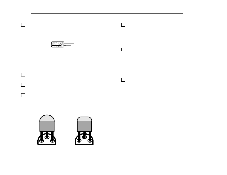
Install and solder the electrolytic capacitors listed below, which
are polarized. Be sure that the (+) lead is installed in the hole marked
with a "+" symbol. The (+) lead is usually longer than the (–) lead, and
the (–) lead is identified by a black stripe (Figure 4-1).
+
-
Figure 4-1
__ C1, 2.2 µF
__ C13, 22 µF
__ C15, 100 µF
__ C28, 220 µF
__ C29, 220 µF
__ C33, 2.2 µF
__ C32, 22 µF
Install and solder ceramic trimmer capacitor C22. Orient the flat
side of this trimmer as shown on its PC board outline.
Using a small flat-blade screwdriver, set C22 so that its
screwdriver slot is parallel to the outline of nearby crystal X2.
Locate Q12 (type PN2222A), which is a small, black TO-92
package transistor. Q12 and other TO-92 transistors may have either of
the two shapes shown in Figure 4-2. The large flat side of the device
must be aligned with the flat side of the component outline. The
part number may be found on either side.
Figure 4-2
Install Q12 near the upper left-hand corner of the PC board. Align
the large flat side of Q12 with its PC board outline as in Figure 4-2.
The body of the transistor should be about 1/8" (3 mm) above the
board; don’t force it down too far or you may break the leads. Bend
the leads of the transistor outward slightly on the bottom to hold it in
place. Solder Q12.
Install the remaining TO-92 package transistors in the order listed
below.
__ Q11, PN2222A
__ Q1, 2N3906
__ Q2, 2N3906
__ Q3, 2N7000
__ Q4, 2N7000
__ Q5, 2N7000
__ Q6, J310
__ Q7, J310
__ Q8, PN2222A
__ Q9, MPS5179
__ Q10, MPS5179
Solder and trim the leads of these transistors.