Elecraft K2 Owner's Manual User Manual
Page 29
28
E
LECRAFT
®
i
CAUTION: The LCD and its pins are fragile—handle
carefully. Do not drop the LCD on a hard surface, as it is made of
glass and may break. Do not remove the protective plastic film from
the front surface of the LCD until later in this section when the front
panel assembly is completed.
Carefully remove the LCD from its packing materials.
i
CAUTION: Do not peel off the thick plastic material on
either side of the LCD, or the LCD will have to be replaced (not
covered under warranty).
Hold the LCD up to a bright light and look at both sides for the
presence of a very thin, clear protective film (like transparent tape). All
LCDs have such film on the front surface of the LCD, which will be
removed in a later step. But the back of some LCDs (not all) may also
have such film, with faintly visible yellow or gray diagonal lines. If
protective film is found on the back side, use a fingernail at one corner
of the LCD to dislodge it, then peel it away.
The LCD has six pins along its lower edge (three on each side),
and 24 pins along the upper edge. Place the LCD in its proper position
on the board but do not solder yet.
The LCD must be seated flat against the diffuser as shown in the
edge view (Figure 5-11). If the LCD does not appear to be seated
correctly, it may be because the backlight LEDs or spacers are mis-
aligned. When the assembly is installed correctly, the LCD’s pins will
all protrude the same distance from the bottom of the board. The leads
may not extend through the solder pad holes.
LCD
Figure 5-11
Solder the four corner pins of the LCD, and then re-check the
alignment of the LCD assembly. If everything looks correct, solder the
remaining pins. LCD pins can be soldered on the top of the board if
they do not protrude from the bottom. If the leads do not reach through
the holes, be sure the solder fills the gap between the lead and solder
pad (see Figure 5-9). After soldering, remove the spacers at each end.
The leads will hold the assembly securely in place.
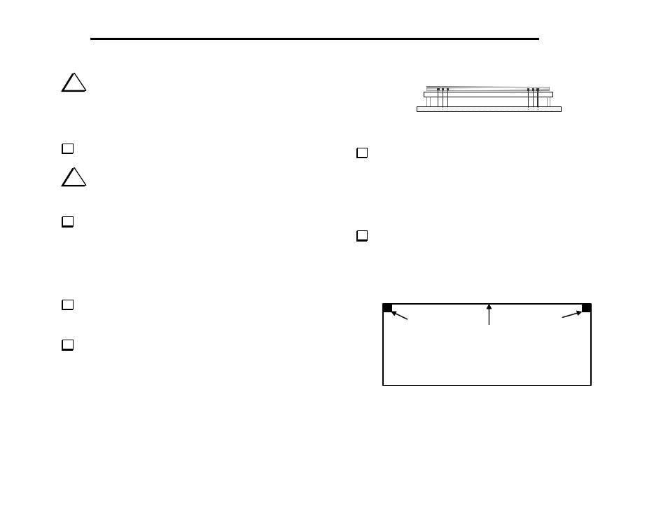
Attach two thin, 1/4" (6.4 mm) self-adhesive rubber pads to the
bottom side of the Front Panel board in the positions indicated in
Figure 5-12. The pads should be placed as close as possible to the
corners, but should not hang over on either edge. These pads establish
the correct spacing for the Front Panel board.
(Bottom of PC Board)
Pad
Pad
Top Edge
Figure 5-12