Elecraft KFL1-2 User Manual
K f l 1 - 2
El
e
c
r
af
t
•
www.
e
l
e
c
r
a
f
t
.
c
om
•
831-662-8345
E
L E C R A F T
K F L 1 - 2
T W O - B A N D F I L T E R B O A R D
Rev. I, December 13, 2005
NOTE:
This instruction sheet should only be used if you are building an additional Filter board for an existing
K1. If you're just starting your K1, discard this sheet and use only the instructions in the Owner's Manual.
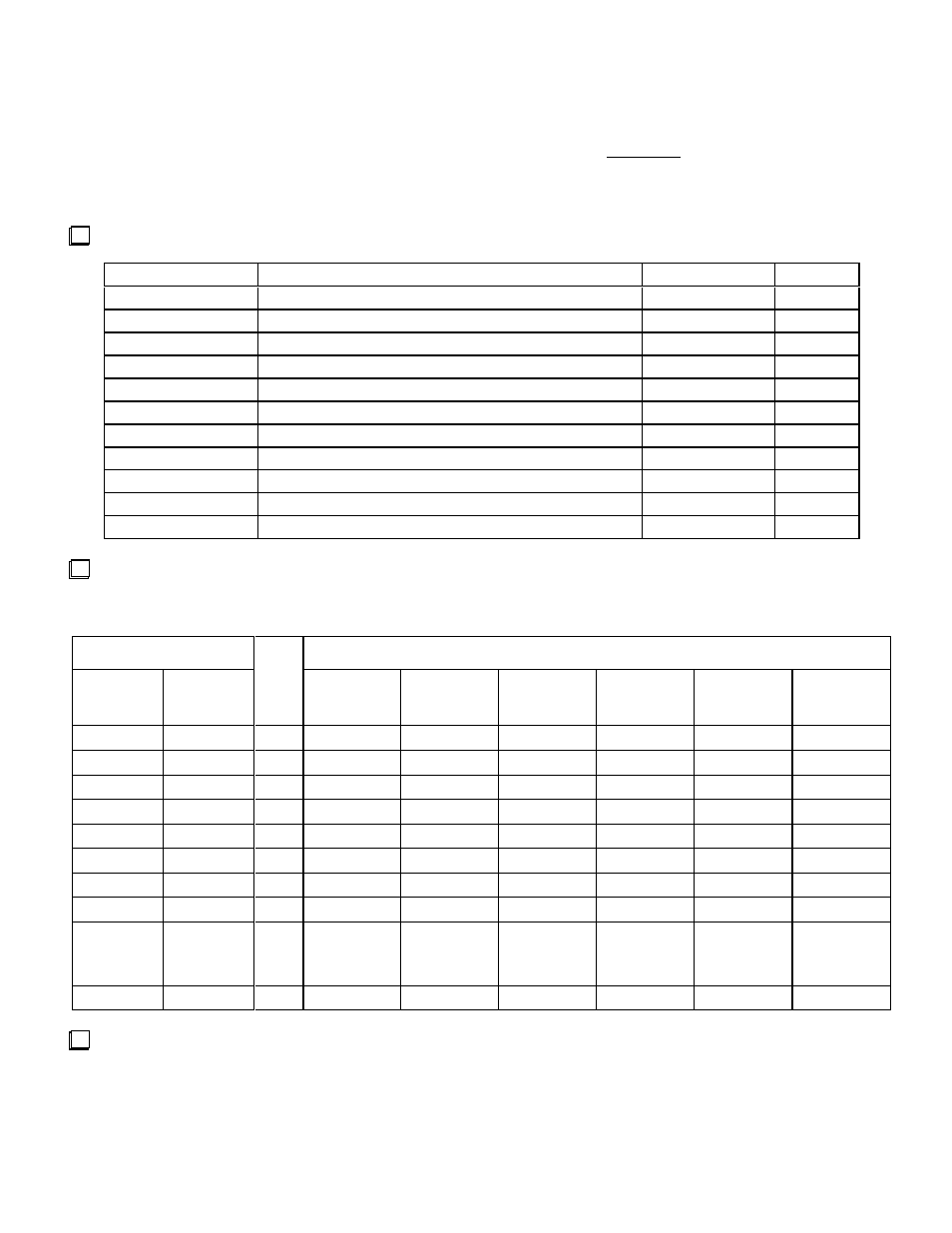
Parts Inventory
Verify that the kit contains the items below. (An inventory of band-specific components appears in the next step.)
Ref. Designators
Description
P/N
Qty.
C29, C30
Capacitor, .001 µF ("102")
E530001
2
C27
Capacitor, .047 µF ( "473")
E530025
1
K1, K2, K3
Latching relay, 5V (in plastic tube)
E640001
3
L1-L8
1 µH slug-tuned inductor (red mark on top, small slot)
E690002
8
P1, P2, P3
8-pin 0.1" connector, male
E620004
3
R1
Resistor, 100
Ω,
1/
4W,
5%
(
BRN-BLK-BRN)
E500010
1
U1
MCU IC, PIC16C620A (alt: 621A), programmed
E610006
1
Z1
Ceramic resonator, 4.000 MHz
E660001
1
Misc.
Socket for U1 (18 pins)
E620031
1
Misc.
#26 Red Enamel Wire
E760002
6 ft
PCB
PC board, 2-band Filter module (label: "K1 FIL 2")
E100095
1
Your KFL1-2
ki
t
s
houl
d
c
ont
a
i
n
t
wo
s
ma
l
l
ba
gs
l
a
be
l
e
d
wi
t
h
t
he
ba
nds
you
s
e
l
e
c
t
e
d,
e
.
g.
“
K1B40”
or
“
40m.
”
Us
e
the table below to inventory these items. Keep the components for the two bands in separate bags. Note: Small
c
a
pa
c
i
t
or
s
ma
y
us
e
a
n
“
R”
r
ather than a decimal point; for example, a 2.7-p
F
c
a
pa
c
i
t
or
mi
ght
be
l
a
be
l
ed
“
2R7”
.
Ref. Designators
Components
Band1___
Band2___
Qty.
80 meters
(3.5 MHz)
40 meters
(7.0 MHz)
30 meters
(10.1 MHz)
20 meters
(14.0 MHz)
17 meters
(18.0 MHz)
15 meters
(21.0 MHz)
C1, C5
C6, C10
2
470 ("471")
390 ("391")
220 ("221")
180 ("181")
100 ("101")
100 ("101")
C2, C4
C7, C9
2
1200 ("122")
330 ("331")
180 ("181")
120 ("121")
82
68
C3
C8
1
10
4.7 or 5
2 or 2.2
1
1
1
C11, C15
C16, C20
2
5600 ("562") 2200 ("222") 1800 ("182") 1000 ("102")
680 ("681")
470 ("471")
C12, C14
C17, C19
2
2700 ("272")
560 ("561")
270 ("271")
120 ("121")
82
56
C13
C18
1
82
10
4.7 or 5
2.7, 3, or 3.3
2 or 2.2
2 or 2.2
C21, C23
C24, C26
2
1200 ("122")
470 ("471")
330 ("331")
220 ("221")
180 ("181")
150 ("151")
C22
C25
1
2200 ("222")
820 ("821")
560 ("561")
390 ("391")
330 ("331")
270 ("271")
L9, L10
(T37-6
core)
L11, L12
(T37-6
core)
2
2.5 µH
28 turns
20" (51 cm)
1.4 µH
21 turns
14" (36 cm)
1.0 µH
18 turns
12" (30 cm)
0.8 µH
15 turns
11" (28 cm)
0.6 µH
13 turns
10" (25 cm)
0.5 µH
12 turns
9" (22 cm)
X1
X2
1
11.500 MHz 15.000 MHz 18/18.1 MHz 22.000 MHz 26.050 MHz 29.000 MHz
80-METER BAND KIT ONLY: The K1B80 kit includes a 10-µF electrolytic capacitor for use at C78 on the RF
board. Install C78 on the bottom of the RF board as shown by its component outline, with the "+" lead oriented as
indicated. Fold the leads down at a 90-degree angle and lay the capacitor flat against the board before soldering.