Preparation for assembly, Overview of the kit – Elecraft K2 Owner's Manual User Manual
Page 8
E
LECRAFT
®
7
3. Preparation for Assembly
Overview of the Kit
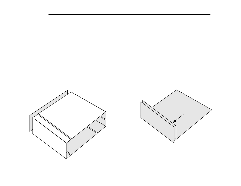
The K2 uses modular construction, both physically and electrically.
This concept extends to the chassis (Figure 3-1). Any chassis element
can be removed during assembly or troubleshooting. (Also see photos
in Appendix D.) If the KPA100 is installed, it takes the place of the
original top cover.
Top Cover
Front
Panel
Side
Panel
Bottom
Cover
Heat
Sink
(Right side panel
not shown)
Figure 3-1
As shown in Figure 3-2, there are three printed circuit boards (PCBs)
in the basic K2 kit: the Front Panel board, Control Board, and RF
board. Option modules plug into the RF or Control board, but are not
shown here.
RF
Front
Panel
Control
Figure 3-2
See also other documents in the category Elecraft Accessories communication:
- KX3 Owner's Manual (58 pages)
- KX3 Assembly Manual (47 pages)
- KX3 Assembly Manual Errata (5 pages)
- KX3-2M (30 pages)
- KX3-PCKT (2 pages)
- KX3 Mobile Installation And Operation Guide (17 pages)
- KX3 Guide for Blind Operators (7 pages)
- KX3 Quick Reference (2 pages)
- K3 Programmers Reference (26 pages)
- KX3 Speaker Grille Instructions (9 pages)
- KXFL3 Filter Option (12 pages)
- KXFL3 Filter Option Errata (2 pages)
- KXAT3 (5 pages)
- KXBC3 (13 pages)
- KXPD3 (4 pages)
- Proset Boom Headset (1 page)
- PX3 Owner's Manual (53 pages)
- PX3 Owners Manual Errata (2 pages)
- KXPA100 Manual (55 pages)
- KXPA100 Assembly Manual (27 pages)
- KXPA100 Assembly Errata (1 page)
- KXPA100 Programmers Reference (24 pages)
- KXAT100 Installation Manual (17 pages)
- KX1 Manual (96 pages)
- KXAT1 (12 pages)
- KXPD1 (7 pages)
- KXB30 (8 pages)
- KXB3080 (20 pages)
- K1 (91 pages)
- K1 1.09 F/W (1 page)
- KNB1 Manual (8 pages)
- KAT1 Manual (15 pages)
- KFL1-2 (2 pages)
- KTS1 (1 page)
- KBT1 Manual (8 pages)
- KBT1 Manual Errata (2 pages)
- K1BKLTKT LCD Mod Kit (6 pages)
- K2 Owner's Manual Errata (1 page)
- K2 PLL (4 pages)
- K2ATOBKIT (15 pages)
- K2ATOBKT (2 pages)
- K2 Keying Modification Instructions (4 pages)
- KPA100 Manual (74 pages)
- KPA100 Shield Upgrade (3 pages)