Elecraft K2 Owner's Manual User Manual
Page 54
E
LECRAFT
®
53
Solder the pins on the bottom of the RF board. Solder a pin at
opposite corners first, then make sure the headers are resting against
the board. If necessary re-heat the pins while pressing the assembly
against the board. When the assembly is in position, solder all 8 pins.
Install U8 (78L05), which has a plastic TO-92 package like a
transistor. U8 is located near the front left corner of the board.
Option-bypass jumpers W5, W2 and W3 are located on the right
side of the board, near the crystal filter. Use component leads to make
these jumpers, or remove the insulation from appropriate lengths of
green hookup wire. These jumpers should be formed so that they lie
flat on the board, and should not touch any adjacent components.
Test points TP1, TP2, and TP3 are round, yellow, single-pin
female connectors. TP1 and TP3 can be found in the synthesizer area
of the board. TP2 is near the SSB option connector, J11. Install and
solder all three test points.
NOTE: There are five 100 µH RF chokes in the kit. If one is slightly
smaller than the others, set it aside to use at RFC15.
Install RF choke RFC13 (100 µH, BRN-BLK-BRN), near the
middle of the board. Orient the first color band to the left
.
Install the receive mixer, Z6 (TUF-1 or TOP-1), below the
"ELECRAFT" label at the middle of the board. Make sure that Z6 is
lined up with its component outline and is flush with the board before
soldering.
Install the electrolytic capacitors in the order listed below, starting
with C60 near the far left-hand edge. Insert the (+) lead of each
capacitor into the hole with the (+) symbol.
__ C60, 100 µF
__ C93, 10 µF
__ C103, 220 µF
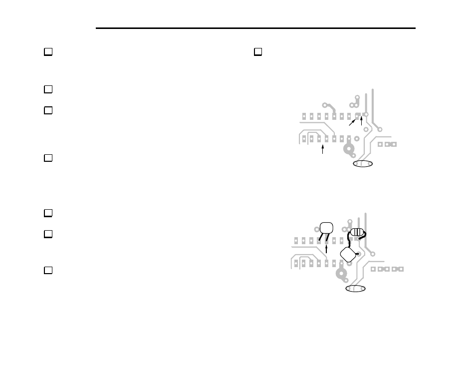
Looking at the bottom of the RF board, locate U4 (MC145170,
near C90). As shown by the "X" in Figure 6-14b, the short trace from
pin 16 of U4 to C89 (on the top side) has been cut at the factory.
C90
X
MC145170
(bottom view)
Pin 16
Figure 6-14b
C90
C91
RFC15
Pin 13
C88
.
001
68
100
Figure 6-14c