Elecraft K2 Owner's Manual User Manual
Page 42
E
LECRAFT
®
41
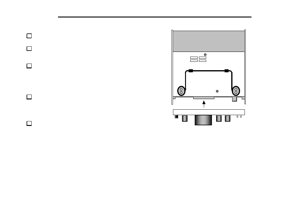
Turn the RF board/side panel assembly upside down. Check for
any untrimmed component leads on the bottom of the board.
Position the bottom cover as shown in Figure 6-10, then secure it
using six chassis screws. (The heat sink and rear feet will not be
installed until Part III when the transmitter is assembled.)
With the entire assembly still upside down or resting on one side
panel, plug the front panel assembly into the RF board (Figure 6-10).
Align the two assemblies so that connector J1 on the bottom of the
front panel PC board mates with P1 on the bottom of the RF board.
The arrow in Figure 6-10 shows the approximate location of P1 on the
RF board.
Once the front panel assembly is in place, the headphone jack (on
the RF board) should be just flush with the front panel. The small
rubber pads in the upper corners of the Front Panel board should be
just touching the 2-D fasteners on the RF board. If this is not the case,
the front panel must be pushed farther in.
Secure the front panel to the side panels and RF board using 4
chassis screws. (Refer to the photos in Appendix D.) You may need to
make slight adjustments to the 2-D fasteners at the top edge.
Figure 6-10