Elecraft K2 Owner's Manual User Manual
Page 57
56
E
LECRAFT
®
RFC16 is wound on an FT37-43 core (dark gray) using 16 turns
of red enamel wire (12", 30 cm). Wind this inductor in the same
manner as RFC14. Install RFC16 vertically, to the right of RFC14.
RFC11 is wound on an FT37-43 core using 20 turns of red
enamel wire (16", 40 cm). Wind this inductor and prepare its leads in
the same manner as RFC14.
Install RFC11 horizontally, on the bottom side of the board, as
shown by its component outline (near the center of the board). The
pads for RFC11 are the two that just touch the outline. Pull the leads
taut on the top to keep the toroid secured to the board, then solder.
i
T5 is a toroidal transformer, with two numbered windings.
These numbers are printed next to each pad on the PC board. T5’s
windings are 1–2 and 3–4.
Locate the large yellow core (T50-6) for use at T5. The core is
1/2" (12.7 mm) in diameter.
Wind the first winding, 1-2, using 16 turns of red enamel wire
(15", 38 cm). This winding must occupy 85% of the core, and will
look very similar to Figure 6-15. Remember that each pass through the
core counts as one turn.
Carefully strip and tin the leads of T5’s 1-2 winding.
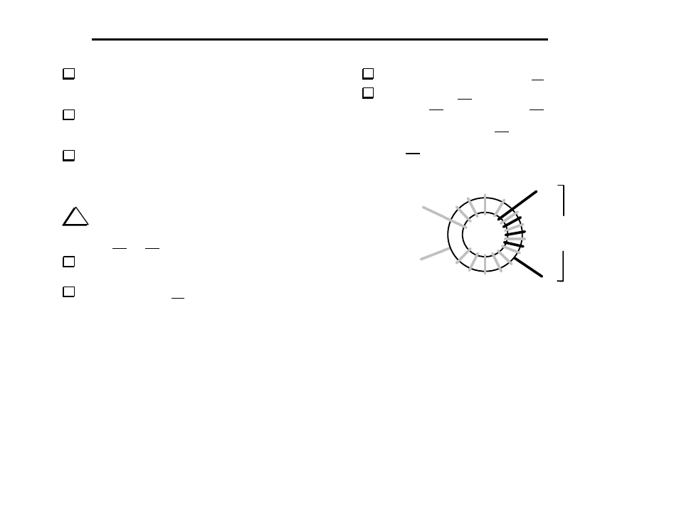
T5’s other winding, 3–4, uses 4 turns of green enamel wire (7",
18 cm). Wind the 3–4 winding on top of the 1–2 winding, interleaving
the turns as shown in Figure 6-16. The turns should be secure, not
loose. Strip and tin the leads of the 3–4 winding.
Note: T5’s 3–4 winding must be wound exactly as illustrated or the
VFO will not function correctly.
Green,
4 turns
1
2
3
4
Figure 6-16