Elecraft K2 Owner's Manual User Manual
Page 61
60
E
LECRAFT
®
Note: A surface-mount RoHS compliant version of the PIN diode used
at D36 is supplied pre-installed on tiny printed circuit board that
mounts in the space originally provided for D36. Install the new part
as follows.
i
ESD-Sensitive! Wear a wrist strap grounded through a 1-
meghom resistor or frequently touch an unpainted metal ground
when handling the SMT1B part in the following steps.
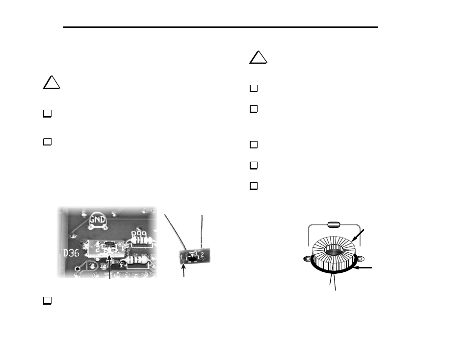
Locate the SMT1B part. Attach two of the 1/4 watt resistor leads
you saved earlier to solder pads 2 and 3 on the board as shown below.
Pad 1 is not used.
Position the SMT1B board as shown with the leads passing
through the solder pads for D36 on the bottom of the RF board. The
lead from pad 3 must go to the pad on the RF board indicated by a
band on the diode outline. That is the pad nearest R99. Note that this
results in the SMT1B markings being upside down compared to the
markings on the RF board as shown below. Adjust the leads as needed
to position the SMT1B board about 1/8” (3mm) above the RF board
and spread the leads to hold it in place.
Pin 3 lead goes to pad at
banded end of outline
Pad 1 not used
On the top side of the RF board, solder both leads and clip them
flush
.
i
The BFO toroid, L33, is supplied pre-wound due to the
large number of turns and very small gauge wire required. When
handling L33, be very careful not to damage the leads.
Locate the rubber stem bumper. Clip off about one-half of the tip
of the stem using diagonal cutters.
L33 is located on the bottom of the board, near the front center.
Place the rubber stem bumper directly on top of L33's component
outline. Flush-trim the leads of all parts under or near L33 so the
stem bumper can sit flat on the PC board.
Locate the pre-wound BFO inductor, L33 (41 µH, 5%). It may be
supplied in a small envelope or bag labeled "L33".
Press L33 down onto the stem bumper as far as it will go.
Position L33 and the stem bumper as shown in Figure 6-20.
Locate resistor R116 (1/8th watt, 5.1 megohm, green-brown-
green). Bend the leads of R116 down at 90-degree angles to match the
spacing of L33's pads (Figure 6-20).
L33
Stem Bumper
R116
Leads
Figure 6-20