Tools – Elecraft K2 Owner's Manual User Manual
Page 11
10
E
LECRAFT
®
Resistors, Chokes, and the Color Code
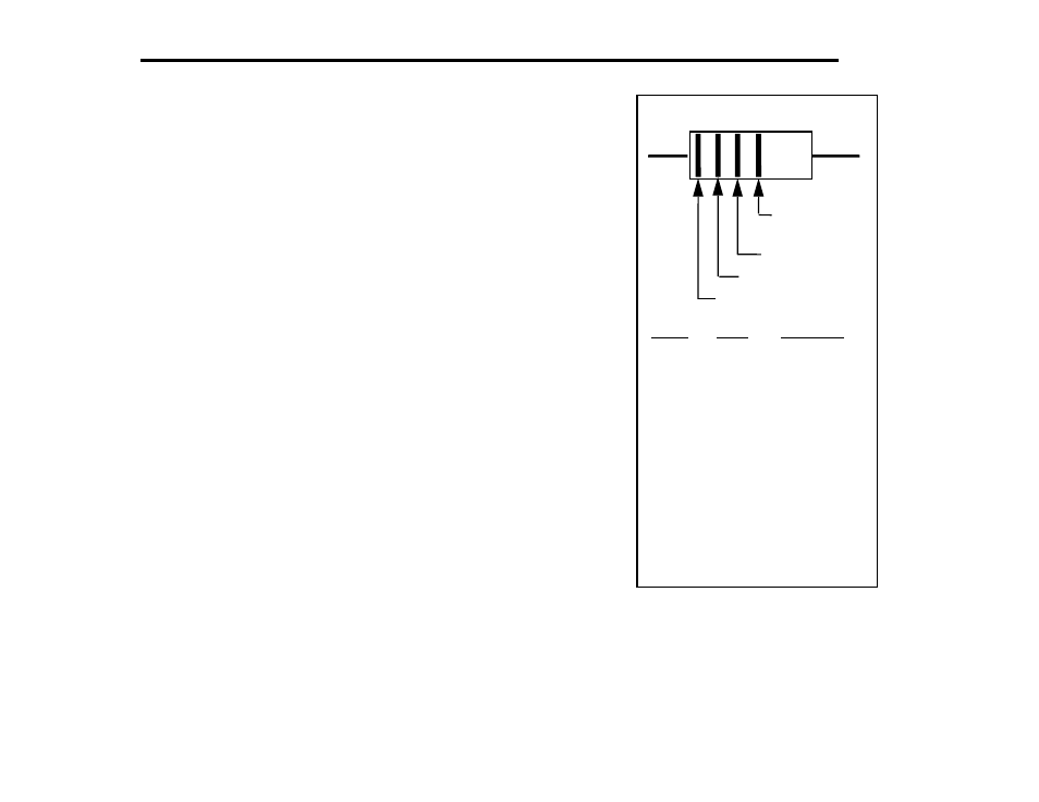
All resistor and RF choke color bands are provided in the text along
with their values. However, it is helpful to familiarize yourself with
the color code to allow you to identify these components without
having to refer to the text or parts list each time.
The color-code chart, Figure 3-4, shows how to read the four color
bands on 5% resistors. 1% resistors are similar, except that they use
five bands (three significant digits, multiplier, and tolerance). For
example, a 1,500 ohm (1.5 k) 5% resistor has color bands BROWN,
GREEN, and RED. A 1.5 k, 1% resistor has color bands BROWN,
GREEN, BLACK, BROWN. The multiplier value is 1 rather than 2 in
the 1% case because of the third significant digit.
Because 1% resistors have color bands that are sometimes hard to
distinguish clearly, you should always check their resistance using an
ohmmeter.
The markings on RF chokes reflect their value in microhenries (µH).
Like 5% resistors, chokes use two significant digits and a multiplier.
Example: an RF choke with color bands RED, VIOLET, BLACK
would have a value of 27 µH.
Tools
The following specialized tools are supplied with the K2:
.050" (1.3 mm) Allen Wrench, short handle
5/64" (2 mm) Allen Wrench, long handle
Double-ended plastic inductor alignment tool
Figure 3-4
Tolerance
(gold = 5%,
silver = 10%)
Multiplier
Second Digit
First Digit
Color
Multiplier
Digit
Black
0
x 1
Brown
1
x 10
Red
2
3
x 100
Orange
x 1K
Yellow
4
x 10K
Green
5
x 100K
Blue
6
x 1M
Violet
7
Gray
8
White
9
Color Code
Silver
--
x .01
Gold
--
x 0.1