Switch functions – Elecraft K2 Owner's Manual User Manual
Page 89
88
E
LECRAFT
®
Switch Functions
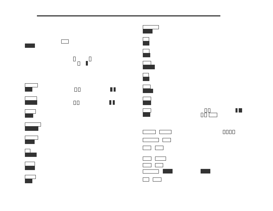
Each pushbutton switch as two primary functions, indicated by the
upper and lower labels.
T A P
a switch to access its upper function;
H O L D
a switch for over 1/2 second to access its lower function.
Numeric Keypad: In addition to their tap/hold functions, ten of the
switches are labeled with digits 0 through 9. A digit can be entered
using either a TAP or HOLD (e.g.
5
, or
5
). In some cases the
difference between the two is significant, as indicated below.
Tap and Hold Functions
B AN D +
select next higher band
R C L
recall memory #
0
-
9
(to start scan, use #
0
-
9
)
B AN D -
select next lower band
S T O R E
store memory #
0
-
9
(to start scan, use #
0
-
9
)
M E N U
enter the menu
E D I T
edit current menu parameter
D I S P L AY
show
voltage/current,
time*, DSP parameters*
R F / AL C
select SSB transmit bargraph mode (RF or ALC)
A N T 1 / 2
toggle between ATU antenna jacks 1 and 2*
T U N E
key transmitter; activates ATU if installed
N B
select noise blanker mode (OFF/NB1/NB2)*
L E V E L
toggle noise blanker threshold (low or high)*
R AT E
select VFO tuning rate (see RATES menu entry)
L O C K
lock/unlock VFO (DP flashes)
M O D E
select operating mode (CW/LSB/USB)
V O X
CW: oper/test; SSB*: PTT/SPEECH (0.2-1.0)
*These functions require option modules; see page 117.
P R E / AT T
turn on preamp or attenuator
S P O T
CW audio spot signal on/off
R I T
turn on RIT (see RIT menu entry, page 108)
P F 1
activate programmable function 1
A/ B
select A or B VFO
R E V
temporary A/B VFO swap (used in SPLIT)
AG C
select FAST/SLOW AGC
C W R V
toggle between CW norm/reverse or USB/LSB
X I T
turn on XIT (see RIT menu entry, page 108)
P F 2
activate programmable function 2
A= B
set both VFO’s to current VFO frequency
S P L I T
toggle between SPLIT and NORMAL transceive
X F I L
select next crystal filter (FL1-4)
AF I L
audio filter mode (OFF, AF1-2, CF1-4, SF1-4)*
M S G
play or chain CW msg #
0
-
8
(to repeat, use #
0
-
8
)
R E C
record CW message #
0
-
8
(
M S G
cancels record)
Two-Switch Combinations (hold both switches)
B AN D +
+
B A N D -
direct frequency entry (e.g., #
7
0
4
0
)
P R E / AT T
+
AG C
AGC on/off (mode letter dec. pt. flashes)
X F I L
+
AG C
display crystal filter # and bandwidth
(plus audio filter setting, if applicable*)
AF I L
+
S P L I T
DSP notch filtering on/off*
AF I L
+
R E C
DSP noise reduction on/off*
D I S P L AY
+
T U N E
override ATU
T U N E
power limit*
R I T
+
X F I L
turn FINE RIT on/off (see page 106)