Lenze EVF9383 User Manual
Page 94
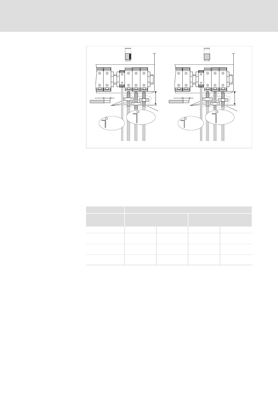
Basic devices in the power range 250 ... 400 kW
Motor connection
5.5
5.5.8
l
5.5−12
EDSVF9383V EN 7.1−04/2012
0
1
BR2
BR2
BR1
BR1
PE
PE
U
U
V
V
W
W
40 mm
40 mm
PE
15-20 Nm
M6
133-176 lb-in
PE
15-20 Nm
M6
133-176 lb-in
U, V, W
25-30 Nm
M8
221-264 lb-in
U, V, W
25-30 Nm
M8
221-264 lb-in
2
2
3
3
max.
300 mm
max.
300 mm
9300VEC036
Fig. 5.5−12
Motor connection example
BR1, BR2 Brake resistors can only be operated with variants V060, V110, V270
and V300
0
Master terminals
1
Slave terminals
2
Connect the motor cable shield with a surface as large as possible to
the control cabinet mounting plate by using the clamps.
3
Conductive surface
Ensure to have the poles right!
Do not exceed the maximum motor cable length!
9300 vector
Installation in accordance with EN 60204−1
U, V, W
PE
Type
[mm
2
]
[mm
2
]
Master
Slave
Master
Slave
EVF9381−EV
EVF9381−EVVxxx
150
2 Ч 50
1)
150
2 Ч 50
1)
95
95
EVF9382−EV
EVF9382−EVVxxx
150
2 Ч 50
1)
150
2 Ч 50
1)
95
95
EVF9383−EV
EVF9383−EVVxxx
240
2 Ч 95
1)
240
2 Ч 95
1)
150
150
1)
Two conductors per path; both conductors must have the same
cross−section
Observe the national and regional legislation
Motor connection
Cable cross−section