2 free configuration of digital outputs, Free configuration of digital outputs – Lenze EVF9383 User Manual
Page 137
Changing the assignment of the control terminals X5 and X6
Free configuration of digital outputs
6.5
6.5.2
l
6.5−3
EDSVF9383V EN 7.1−04/2012
6.5.2
Free configuration of digital outputs
ƒ The digital outputs X5/A1 ... X5/A4 can be freely linked with internal
digital signals.
ƒ One signal source can be linked with several targets.
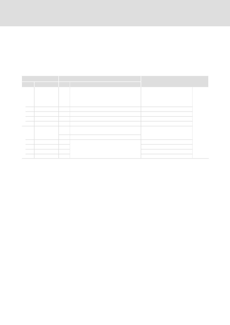
Codes for parameter setting
Code
Possible settings
IMPORTANT
No.
Name
Lenze Selection
C0117
s
^ Selection list 2
Configuration of digital inputs
signals, function block DIGOUT
A change of the basic
configuration in C0005 changes
the signal assignment!
^
6.5−3
See System
Manual
(extension)
1 CFG: DIGOUT1
15000 DCTRL−TRIP
Terminal X5/A1
2 CFG: DIGOUT2
10650 CMP1−OUT
Terminal X5/A2
3 CFG: DIGOUT3
500
DCTRL−RDY
Terminal X5/A3
4 CFG: DIGOUT4
5003 MCTRL−MMAX
Terminal X5/A4
C0118
0
High active
HIGH level is
active
Inversion of digital output signals,
function block DIGOUT
1
LOW active
LOW level is active
1 DIGOUT1 pol
1
Terminal X5/A1
2 DIGOUT2 pol
1
Terminal X5/A2
3 DIGOUT3 pol
0
Terminal X5/A3
4 DIGOUT4 pol
0
Terminal X5/A4
The digital outputs can be linked with internal digital signals by entering the
selection figure of the internal signal into corresponding subcode of C0117.
Example
ƒ C0117/2 = 505
ð signal source for X5/A2 is the status message
"direction of rotation" (DCTRL−CW/CCW)
ƒ Terminals (X5/A1 ... X5/A4):
– HIGH = +12 V ... +30 V
– LOW = 0 V ... +3 V
ƒ Response times: 1 ms
In C0118 you can define the active signal level (HIGH level active or LOW level
active) for the terminals X5/A1 ... X5/A4.
Example
ƒ C0118/2 =1
ð With LOW level at X5/A2 the motor rotates in CW
direction (with in−phase motor connection)
Description
Linking signals
Signal level
Inverting the signal level