2 fuses and cable cross-sections, Fuses and cable cross−sections – Lenze EVF9383 User Manual
Page 405
Fuses and cable cross−sections
10.2
l
10.2−1
EDSVF9383V EN 7.1−04/2012
10.2
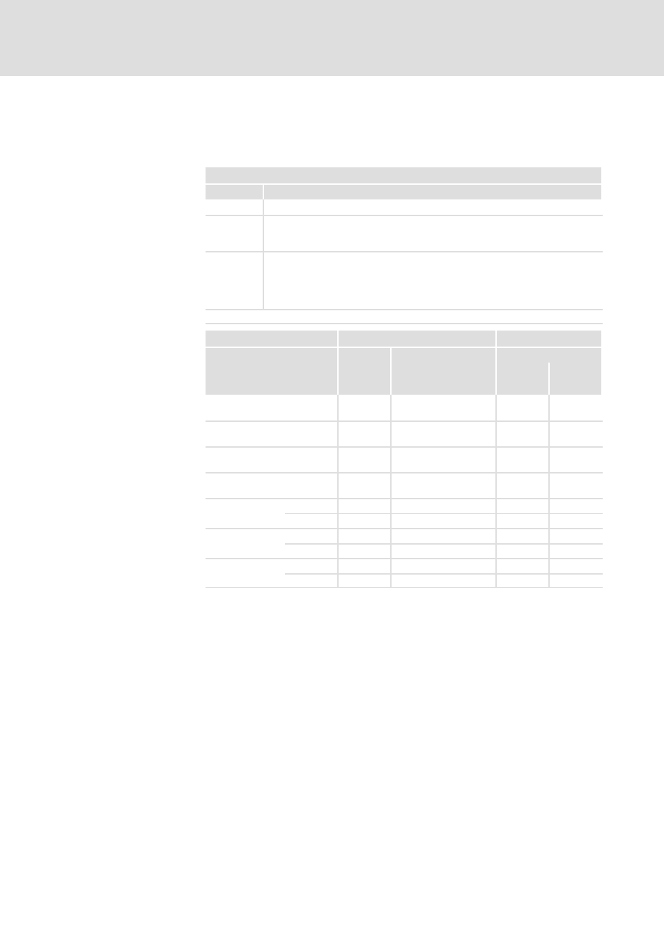
Fuses and cable cross−sections
A DC supply is only possible for the variants V210, V240, V270, V300.
Supply conditions
Range
Description
Mains
DC 480 ... 800 V
Fuses
l
Only semiconductor fuses.
l
If you are using fuses other than those indicated, other fuse currents and
cable cross−sections may result.
Cables
l
DC cables (+U
G
, −U
G
) must always have two−pole insulation.
l
Laying systems B2 and C: Use of PVC−insulated copper cables, conductor
temperature < 70 °C, ambient temperature < 40 °C, no bundling of cables or
cores, three loaded cores. The information is a recommendation. Other
designs/laying systems are possible (e.g. according to VDE 0298−4).
Observe all national and regional regulations!
9300
Fuse
Cable cross−section
Quantity
Rated fuse current
Laying system F
+U
G
, −U
G
PE
Type
[A]
[mm
2
]
[mm
2
]
EVF9335−EVV2xx
EVF9335−EVV300
1
400
2 × 50
1)
95
EVF9336−EVV2xx
EVF9336−EVV300
1
400
2 × 50
1)
95
EVF9337−EVV2xx
EVF9337−EVV300
2
350
2 × 95
1)
95
EVF9338−EVV2xx
EVF9338−EVV300
2
400
2 × 95
1)
150
EVF9381−EVV2xx
EVF9381−EVV300
Master
1
400
2 × 50
1)
95
Slave
1
400
2 × 50
1)
95
EVF9382−EVV2xx
EVF9382−EVV300
Master
2
350
2 × 95
1)
95
Slave
2
350
2 × 95
1)
95
EVF9383−EVV2xx
EVF9383−EVV300
Master
2
400
2 × 95
1)
150
Slave
2
400
2 × 95
1)
150
1)
Two conductors per path; both conductors must have the same cross−section
Installation in accordance
with EN 60204−1