Configuration – Lenze EVF9383 User Manual
Page 257
Configuration
Function blocks
Internal motor control with vector control (MCTRL2)
8.2
8.2.7
l
8.2−41
EDSVF9383V EN 7.1−04/2012
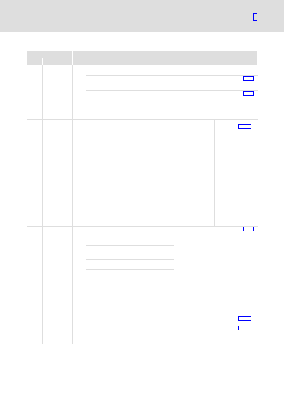
Codes for parameter setting
Code
Possible settings
IMPORTANT
No.
Name
Lenze Selection
C0006
s
Op mode
5
Selection of the operating mode
for the motor control
1
vector ctrl
Vector control
without or with
speed feedback
In case of the first selection enter
the motor data and identify them
with C0148.
^ 6.8−8
5
V / f
V/f characteristic
control
Commissioning without
identification of the motor data is
possible
l
Advantage of identification
with C0148: Improved smooth
running at low speeds
^ 6.8−4
C0010 N
min
0
0
{1 rpm}
36000
l
Reference value
for the absolute
and relative
setpoint selection
for the
acceleration and
deceleration
times
l
C0059 must be
set correctly
l
Set C0010 <
C0011
l
C0010 is only
effective in case
of analog setpoint
selection via AIN1
Important: For
parameter setting
via interface, major
changes in one step
should only be made
when the controller
is inhibited.
Minimum
speed
^
6.10−1
C0011 N
max
3000 0
{1 rpm}
36000
Maximum
speed
C0018 fchop
6
Switching frequency of the
inverter
l
General rule: The lower the
switching frequency the
– lower the power loss
– higher the noise generation
– better the concentricity
factor
l
Observe derating indications
for high switching frequencies
l
The max. output frequency
(f
max
) is:
– fchop = 4 kHz
Þ
f
max
= 300 Hz
– fchop = 2 kHz
Þ
f
max
= 150 Hz
– fchop = 1 kHz
Þ
f
max
= 150 Hz
^ 6.9−1
1
1 kHz sin
loss−optimised
2
2 kHz sin
concentricity−opti
mised
3
4 kHz f_top
power−optimised
4
4 kHz sin
noise−optimised
6
4/2 kHz sin
noise/concentricit
y−optimised with
automatic
change−over to
low switching
frequency
C0019 Thresh nact=0
0
−36000
{1 rpm}
36000 Operating threshold − automatic
DC injection brake (Auto−GSB)
l
Falling below the threshold in
C0019 activates automatic DC
injection braking when the
holding time set under C0107 >
0
^
8.2−25
^
8.2−40