Festo Электромотор MTR-DCI User Manual
Page 66
3. Installation
3-10
Festo P.BE-MTR-DCI-DN-EN en 1209a
Logic voltage
In operation, the logic voltage is connected via the FBA-...
Fieldbus adapter
separately to the load voltage.
For MTR-DCI-42, 52, 62: For commissioning purposes, the
logic voltage can be optionally connected
together with the
load voltage via the power supply connection. In normal oper-
ation, the logic voltage
must be connected separately to the
load voltage via the FBA-... Fieldbus adapter.
With separate supply, the load voltage can be switched off
e.g. in the case of EMERGENCY-STOP, with logic voltage con-
tinuing to be applied and the controller remaining functional
and retaining its reference position.
Switch-on sequence
Do
not switch on the logic voltage after the load voltage,
since this may cause the MTR-DCI to switch off and back on
again (= reset).
Logic voltage failure
If the logic voltage fails, the controller will switch off.
For MTR-DCI-42, 52, 62: if the load voltage is still active, the
controller will switch back on but will lose its reference posi-
tion.
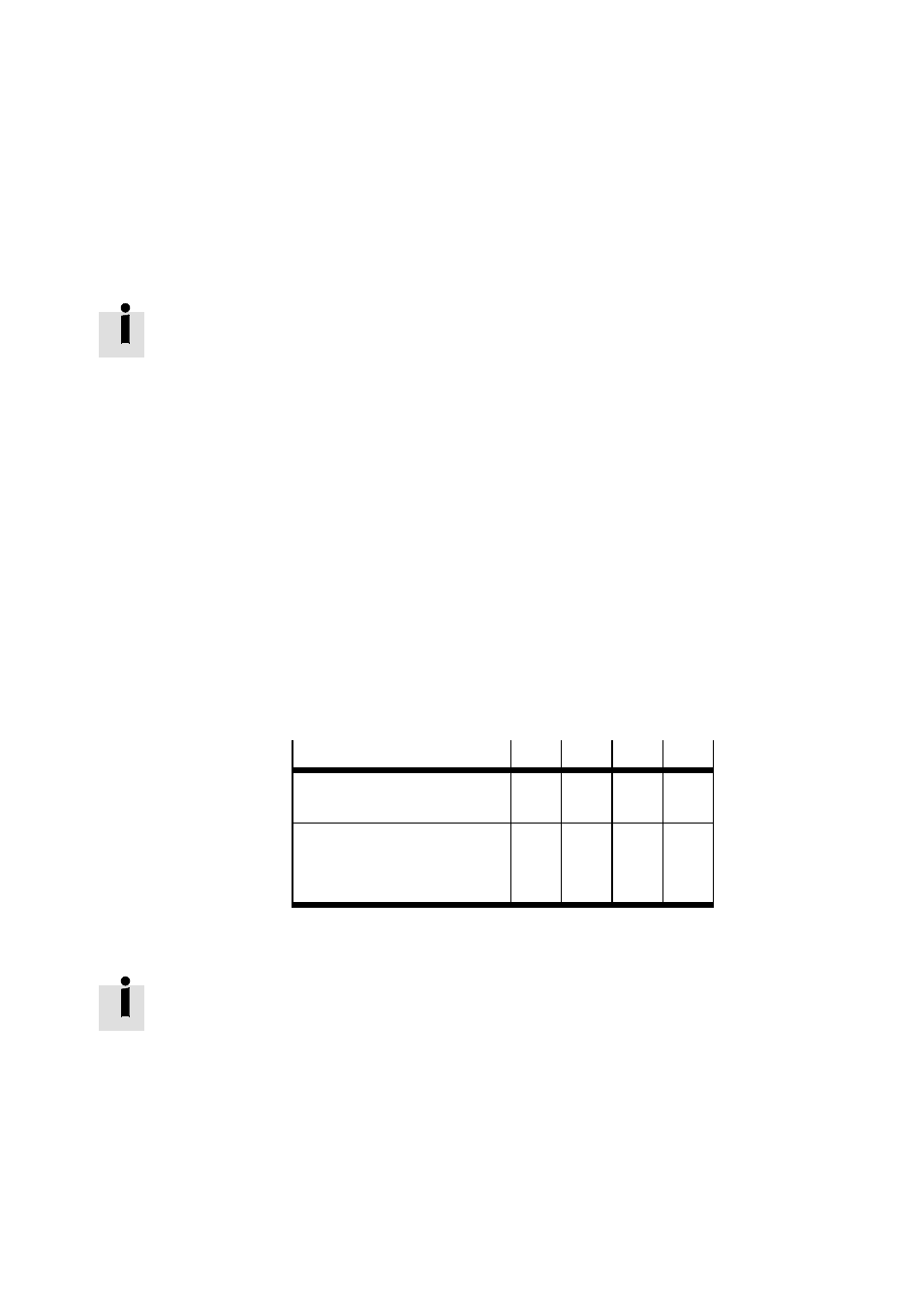
Logic voltage supply
32
42
52
62
–
In operation:
via Fieldbus adapter FBA-...
x
x
x
x
–
For commissioning and para-
meterisation:
optionally via the power supply
connection
—
x
x
x
Tab. 3/5: Logic voltage supply
Information on the connection specifications of the Fieldbus
adapter is provided in chapter 3.6.1 and also in the installa-
tion manual of the Fieldbus adapter.