Horner APG SmartStack I/O HE800PBS600/HEPBS600 User Manual
Page 43
DP Slave
MAN0575-04-EN
PAGE 43 of 97
© Horner APG.This drawing is the property of Horner APG. And shall not be disclosed or reproduced except as specifically authorised.
Profibus Modules User Manual
EO 09-0009
User program monitoring
The Watchdog time determines how long the device will wait for an application triggering until it
resets all outputs to zero. For current firmware versions, this must be set to zero.
Start-up behaviour after system initialisation
When Automatic release of the communication by the device has been chosen, then the
Slave is ready to communicate with the Master. When Controlled release of the
communication by the application program has been chosen, then the user must release the
communication by means of a defined release procedure. The current firmware version expects
the ‘Automatic release’ option to be chosen.
Configuration data
For Standard, the configuration of the Slave is compared with that from CHK_CFG_TELEGRAM
from the Master.
For Forced by CHK_CFG_TELEGRAM, the configuration of the Slave is transferred from the
Master to the Slave with the CHK_CFG_TELEGRAM. The normal (default) is ‘Standard’.
DPV1 Parameter
Class 1 Buffer length: This setting defines the size of the buffer for DPV1 class 1 services in the
DP Slave. The length determines the maximum data count that can be transferred in a DPV1
class 1 telegram. From the buffer size set here, 4 Bytes are reserved for the transfer of the DPV1
administration data and these are not available for transfer of user data.
Valid values for the length of class 1 buffer are in the range of 4 .. 244. Alterations of the size of
the buffer can only be set in the Slave configuration dialog, if the DPV1 services for the Slave
have been activated.
Class 2 Buffer length: The length of the DPV1 class 2 buffer that is to be established must be
defined in this field. Similar to the configuration of the class 1 buffer, here, 4 Bytes of the given
buffer length are reserved for the transfer of the DPV1 administration data. The maximum
transferable user data count is reduced by these 4 Bytes. Values in the range 48 .. 244 can be
defined for the DPV1 class 2 buffer lengths. If the value 0 is entered, then the DP Slave lays
down no DPV1 class 2 buffer. In this case, the DPV1 class 2 services of the Slave are not
available.
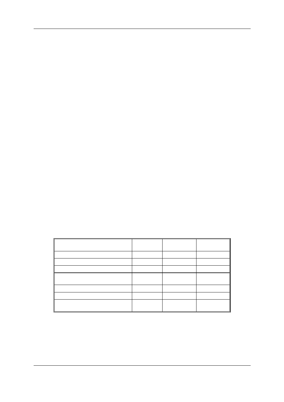
Note: Please note that the settings of the class 1 and class 2 buffer lengths influence the usable
data width in the cyclical I/O region. This limitation is caused by the restricted memory space in
the slave device. The purpose of the examples in the following table is to show how to estimate
the usable buffer length and I/O data width.
Example
Cyclic I/O
data
DPV1 class 1
buffer
DPV1 class 2
buffer
Maximum I/O data
368
60
0
Maximum DPV1 class 1 buffer
304
244
0
Maximum DPV1 class 2 buffer
296
0
244
Maximum DPV1 class 1 buffer and
Maximum DPV1 class 2 buffer
200
244
244
128 Bytes for DPV1 class 1 buffer
344
128
0
128 Bytes for DPV1 class 2 buffer
328
0
128
128 Bytes for DPV1 class 1 buffer and
128 Bytes for DPV1 class 2 buffer
280
128
128
Table 9: Buffer length for DPV1
In the case that the given lengths for buffer and I/O data exceeds the memory space available, the DP
Slave will report an error after the configuration download. This error message can be seen in the
extended device diagnostic of the Slave in the ’SPC3’ section under ‘Last Error’. If the error code 75
is entered there, more memory has been requested in the PROFIBUS-ASIC than is available.
Therefore, the DPV1 buffer length or I/O data width should be reduced and the configuration
download should then be carried out again.