Horner APG SmartStack I/O HE800PBS600/HEPBS600 User Manual
Page 27
Profibus configuration
MAN0575-04-EN
PAGE 27 of 97
© Horner APG.This drawing is the property of Horner APG. And shall not be disclosed or reproduced except as specifically authorised.
Profibus Modules User Manual
EO 09-0009
Note 2: With the SmartStack Slave, the input or output data at the bus are taken directly into the
Dual-port memory. The offset addresses refer to the Master.
There are two types of Slaves. A simple Slave has a fixed data length. The data length of a
modular Slave is configurable. A modular Slave can be understood as a combination of a simple
Slave with a Station address.
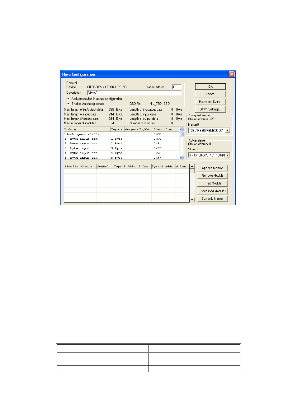
Figure 6: Settings > Slave Configuration
The selection list (upper list) shows all possible modules of the Slave. In the case of a simple Slave,
one module is shown and this is automatically copied into the configuration list (lower list). In the case
of a modular Slave, the user must select the required modules and transfer these by means of a
double click or transfer it using the Append Module button into the configuration list (lower list).
If a module consists of several sub-modules, then each sub-module is shown in the configuration list
(lower list) in a separate row. This is displayed by the number in the Slot column. The Index column
shows a sequential number for sub-modules.
For configuration of the modules (selection of the modules) of a Slave, proceed as follows:
Transfer all the required modules from the selection list (upper list) into the configuration list (lower
list). The sequence of the modules in the configuration list (lower list) is important and must be in
agreement with the Slave. Typically, the sequence follows the actual physical sequence. There are
Slaves to which this rule does not apply and where first analogue modules and then digital modules
must be entered, independent of their actual sequence.
In the configuration list (lower list) allocate the address of each module to the process depiction
memory. The address is entered separately in the Type and Addr columns for Inputs and Outputs.
The I/O addresses can be allocated by the user or can be automatically assigned by SyCon. For this
purpose Auto addressing must be activated or deactivated in the Master Configuration window:
Auto addressing activated
Auto addressing deactivated
Auto addressing
(by SyCon)
Manually addressing
(by the user)
The addresses will be allocated beginning
The address 0 is shown in the I Addr or O