Horner APG SmartMod HE359RTD100 User Manual
Smartmod rtd input module
MAN0840-04-EN
Specifications / Installation
__________________________________________________________________________________________________________________________________________________________________
5/11/2009
Page 1 of 2 ECN # 950
1
Specifications
RTD100
RTD100
Number of
Channels
4
Conversion Time
(PLC Update
Rate)
Determined
by
Communicat-
ions w/OCS
Input Ranges
RTD Pt-100, Ni-100,
Pt-1000, & Ni-1000,
0-2000ohm,
0-500ohm
(PT, .00385)
Terminal Type
Screw Type,
Removable
Resolution
0.1C or 0.1ohm
Storage Temp.
-40
°
to 85
°
Celsius
Operating Temp.
-10
°
to 60
°
Celsius
RTD
Excitation
Current
350microamp,
typical
Relative Humidity
5 to 95%
Non-
condensing
Accuracy
+/-0.1% F.S.
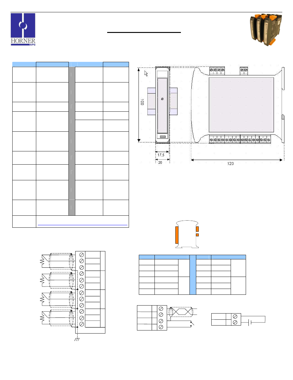
Dimensions
WxHxD
17.5mm x
100mm x
120mm
0.69” x 3.94”
x 4.72”
External
Power Supply
Voltage
10-30Vdc
Weight
150g (6 oz.)
Required
Power
(Steady State)
30mA @ 24Vdc,
typical
Communications
Modbus/RTU
(binary)
RS-485 half
duplex
Required
Power
(Inrush)
Negligible
Factory Default
Communications
Parameters
38400 baud,
N, 8, 1, no
h/s
Default
Modbus ID 1
Isolation
2000Vac for 60
seconds
(Input/Power &
Input/Comms)
Supported
Modbus
Commands
1,2,3,4,5,6,8,
15,16
CE & UL
Compliance
See Compliance Table at
http://www.heapg.com/Pages/TechSupport/ProductCert.html
2
Wiring – I/O
Pin #
RTD100
Pin #
RTD100
1
GEN
7
GEN
2
IN
8
IN
3
REF
IN 0
9
REF
IN 2
4
GEN
10
GEN
5
IN
11
IN
6
REF
IN 1
12
REF
IN 3
SmartMod
RTD Input Module
HE359RTD100
0.1C or 0.1ohm Resolution
Dimensions in inches are 0.69”W x 3.95”H x 4.72”D
Note: Number of I/O terminal connections vary from model to model
D-
D+
GND
INIT
A
B
C
D
V-
V+
I
J
10-30Vdc
Notes:
Both ends of the RS-485 network should be terminated with a 100ohm, 1/4W, 1% resistor. Many OCS
controllers feature dip switches or jumpers which enable appropriate termination if the OCS is located on
a network end.
Wiring RS-485
Wiring DC IN
1
2
3
4
5
6
7
8
9
10
11
12
GEN
IN
REF
IN
0
GEN
IN
REF
IN
1
GEN
IN
REF
IN
2
GEN
IN
REF
IN
3
I/O
RS-485
DC IN