Setting up fcoe connectivity to 3par arrays – HP MPX200 Multifunction Router User Manual
Page 138
6.
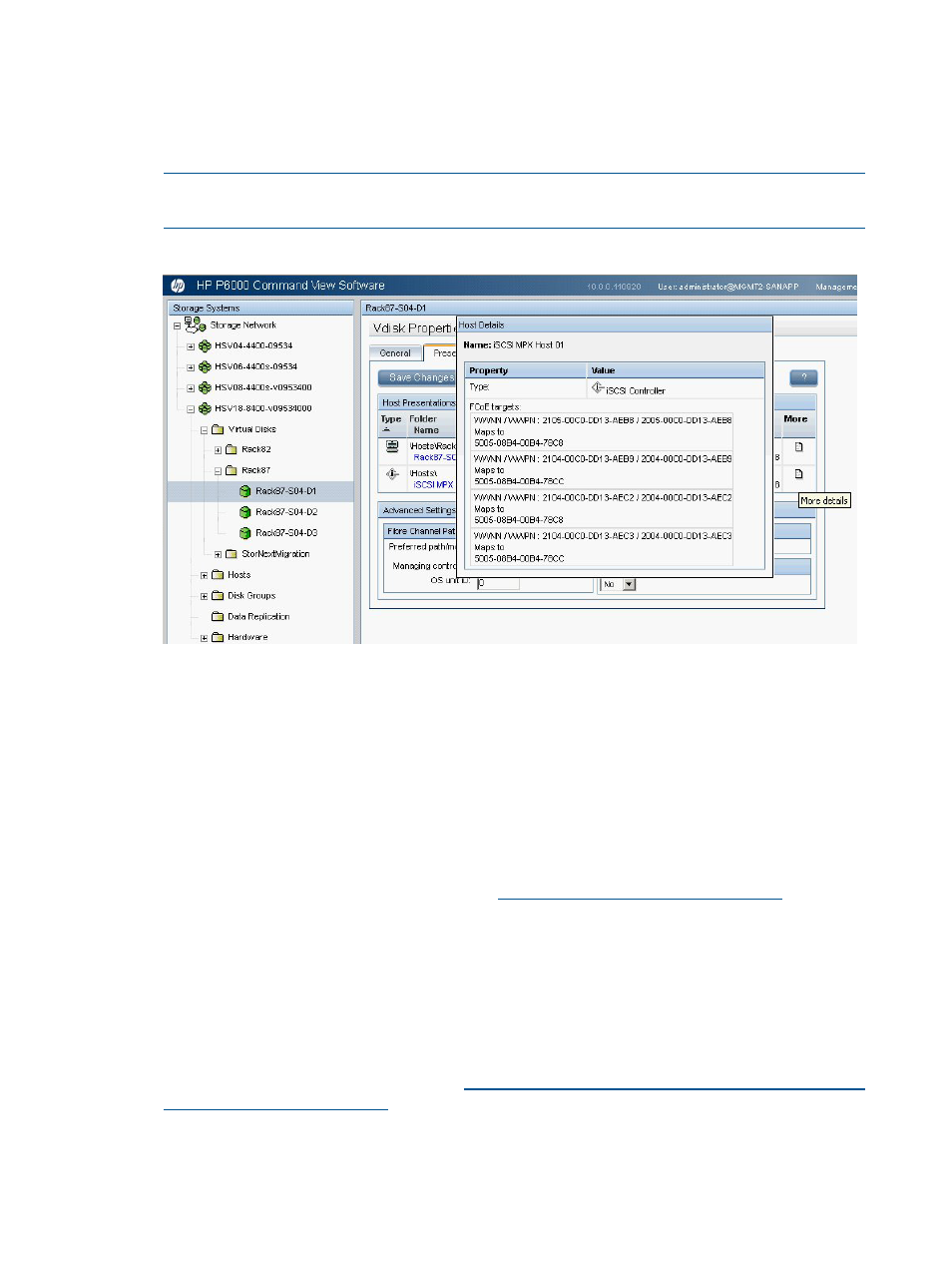
Add FCoE targets to the FCoE zone.
After the first virtual disk/LUN is presented, the FCoE targets are dynamically created and
mapped. In
, if move your cursor over the More icon, a Host Details
pop-up appears, showing the FCoE targets and how they map to the P6000 EVA ports. These
FCoE WWNNs must be added to the FCoE zone created in
NOTE:
This step is not required for subsequent Vdisk/LUN assignments for the same or
additional hosts.
Figure 116 Host Details display
Setting up FCoE connectivity to 3PAR arrays
Before executing the following procedure, ensure that MPX200 host has been created in the InForm
Management Console as described in
“Managing MPX200 iSCSI for 3PAR StoreServ Storage”
.
To set up for FCoE:
1.
Configure the FCoE-enabled converged network switch. Depending on the switch vendor, you
might need to configure the ports for FCoE use.
For information about switch setup, see the Fibre Channel Over Ethernet chapter of the HP
SAN Design Reference Guide, available at:
2.
Verify that the MPX200 10-GbE ports are connected to the FCoE switch as described in
.
3.
Set up the CNA:
a.
Install the CNA driver kit.
b.
Depending on the CNA vendor, use the available management tool to determine the
WWNN/WWPN for each port on the CNA.
For more information about CNA configurations, see the HP Emulex Converged Network
Adapter Installation Guide, available at
.
4.
Create a zone with the MPX200 FCoE ports and the CNA on each fabric.
This registers the CNA worldwide name in the MPX200.
138
MPX200 FCoE feature description