Understanding l3 dsr – Brocade Virtual ADX Server Load Balancing Guide (Supporting ADX v03.1.00) User Manual
Page 33
Brocade Virtual ADX Server Load Balancing Guide
17
53-1003247-01
Overview
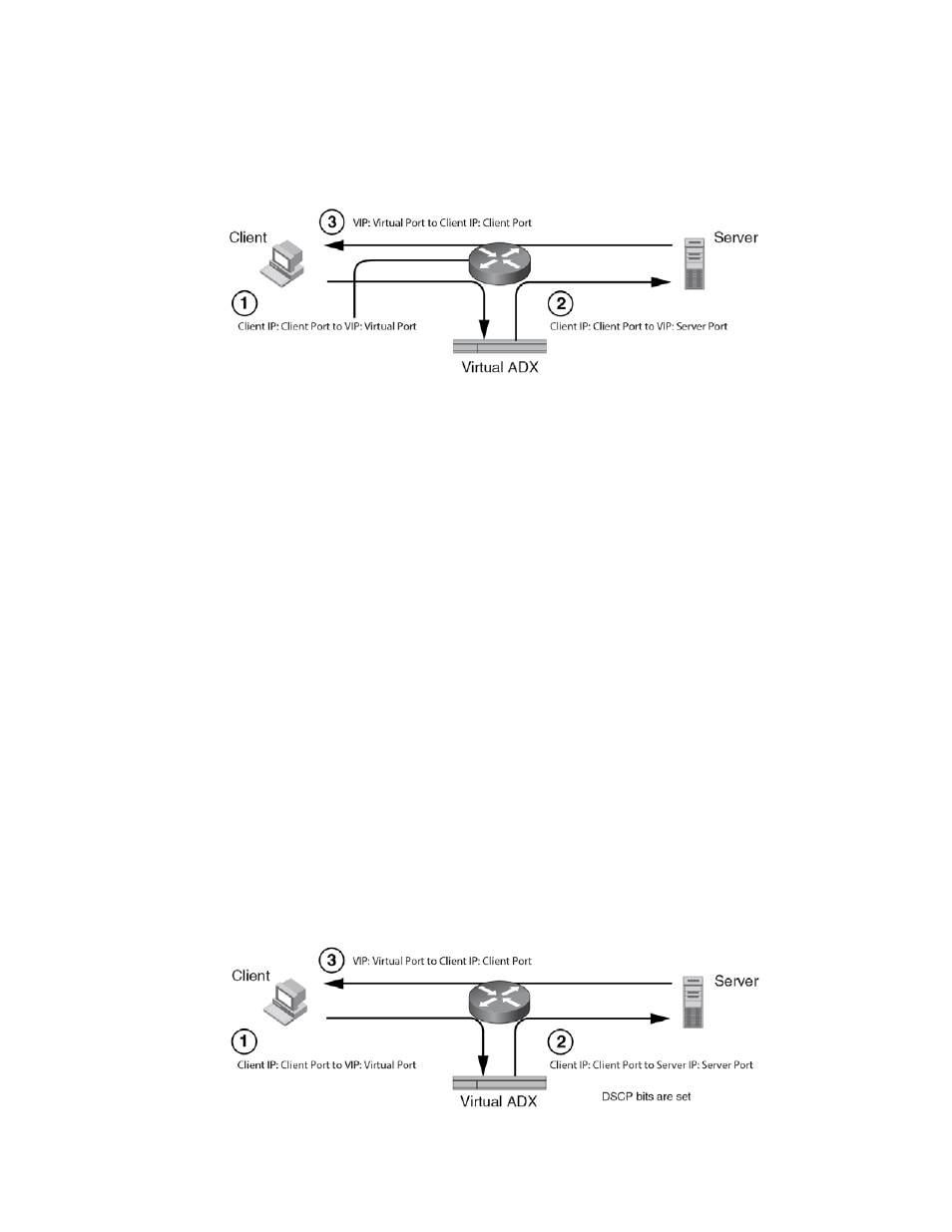
2
shows an example of a Brocade Virtual ADX deployed in an L2 DSR configuration.
FIGURE 3
Brocade Virtual ADX in an L2 DSR configuration
The example above shows the flow of packets in which the Brocade Virtual ADX and the real
servers are Layer 2 connected.
1. The client sends a packet to an VIP on the Brocade Virtual ADX.
2. The Brocade Virtual ADX forwards the packets to the loopback address on the real server.
3. The real server then sends the packet directly to the client.
L2 DSR can be configured on an individual TCP or UDP port basis when you configure your virtual
servers. For a complete discussion of L2 DSR and a configuration example, refer to
Understanding L3 DSR
As with L2 DSR, a Brocade Virtual ADX configured for L3 DSR enables application servers to
respond directly to the clients resulting in faster server-to-client response times and increased
connection capacity for the Brocade Virtual ADX.
But unlike L2 DSR, which requires that the Brocade Virtual ADX servers and clients be directly
(Layer 2) connected, in an L3 DSR configuration the servers and clients can be connected using a
router.
For L3 DSR to work, the Brocade Virtual ADX must be able to inspect the DSCP field of incoming
packets and modify it to a configured value. Also, the real server must be configured to use the VIP
address as the source IP address in the response if the received packet has a matching DSCP field
value.
A typical configuration includes servers that are one hop away where the Brocade Virtual ADX has
additional intelligence to handle health checks response packets.
shows an example of a
Brocade Virtual ADX deployed in an L3 DSR configuration.
FIGURE 4
Brocade Virtual ADX in an L3 DSR configuration