IAI America XSEL-KE User Manual
Page 30
15
Part 1 Installation
(14) Mode switch
This alternate switch with lock is used to command a controller operation
mode. To operate the switch, pull it toward you and tilt.
Tilting the switch upward will select MANU (manual mode), while tilting it
downward will select AUTO (auto mode). Teaching can be performed only
in the MANU mode, but auto program start is not enabled in the MANU
mode.
(Refer to the types of manual operations explained on p.353.)
(15) Teaching-pendant
connector
When an optional teaching pendant or PC is connected, this D-sub, 25-
pin connector will be used to input program and position data in the
MANU mode.
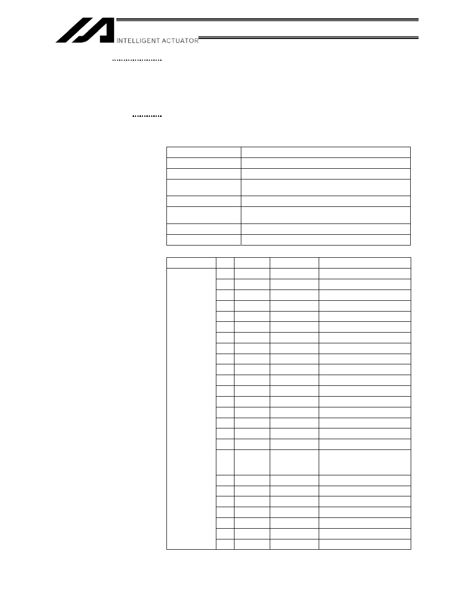
Interface Specifications of Teaching Serial Interface
Item Description
Connector name
TP
Connector
DSUB-25 XM3B-2542-502L (Omron)
Communication
method
RS232C-compliant, start-stop synchronous method
Baud rate
38.4 kbps max.; half-duplex communication
Maximum connection
distance
10 m (38.4 kbps)
Interface standard
RS232C
Connected to
X-SEL teaching pendant
Interface Specifications of Teaching Serial Interface
Item No.
Direction
Signal
name
Description
1
FG
Frame
ground
2
Out TXD
Transmitted
data
3
In RXD
Received
data
4
Out RTS
Request
to
send
5
In
CTS
Clear to send
6
Out DSR
Equipment
ready
7
SG
Signal
ground
8
9
In
Connection
prohibited
10
In
Connection
prohibited
11
12
Out EMGOUT
Emergency
stop
13
In EMGIN
14
15
Out
Connection
prohibited
16
Out
Connection
prohibited
17
Out
Connection
prohibited
18
Out VCC
Power output
(5-V power source for
teaching pendant)
19
In ENBTBX
Enable
input
20
In DTR
Terminal
ready
21
22
23
Out EMGS
Emergency-stop
status
24
Terminal
assignments
25
SG
Signal
ground
(15)
(16)