IAI America XSEL-KE User Manual
Page 28
13
Part 1 Installation
(8) Brake switch
This alternate switch with lock is used to release the axis brake. To
operate the switch, pull it toward you and tilt.
Tilting the switch upward (RLS side) will release the brake forcibly, while
tilting it downward (NOM) will enable an automatic brake control by the
controller.
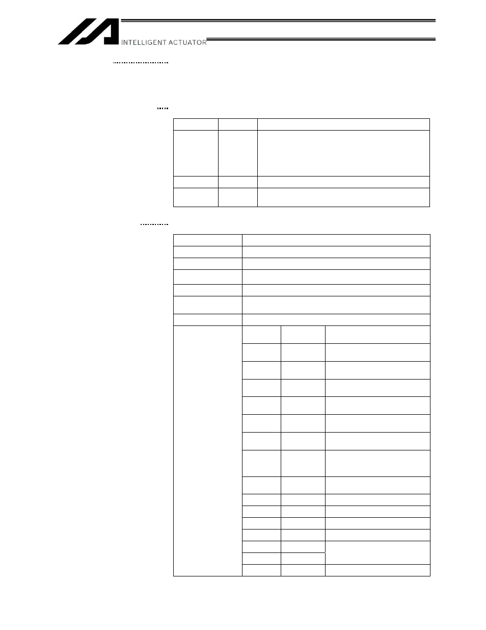
(9) Axis-driver status LEDs
These LEDs monitor the operating status of the driver CPU that controls
the motor drive. The following three LEDs are provided.
Name
Color
Meaning when lit
ALM Orange
The driver is detecting an error.
This LED blinks when the current limiter setting
is exceeded. However, a blinking ALM LED
does not indicate a problem, unless an error is
present.
SVON
Green
The servo is on and the motor is being driven.
BAT ALM
Orange
The voltage of the absolute-data backup
battery is low.
(10) Encoder connector
7KLVSLQ'VXEFRQQHFWRULVXVHGWRFRQQHFWWKHDFWXDWRU¶VHQFRGHU
Encoder Connector Specifications
Item Description
Connector name
PG
Connector
High-density D-sub, 15-pin (female)
Maximum connection
distance
10 m
Interface standard
Conforming to RS422
Connected to
Actuator
(Built-in encoder unit inside the actuator)
Connection cable
Dedicated PG cable
Pin No.
Signal
name
Description
1 A+
Phase-A differential + input
(Phase U+)
$±
3KDVH$GLIIHUHQWLDO±LQSXW
3KDVH8±
3 B+
Phase-B differential + input
(Phase V+)
%±
3KDVH%GLIIHUHQWLDO±LQSXW
3KDVH9±
5 Z+
Phase-Z differential + input
(Phase W+)
=±
3KDVH=GLIIHUHQWLDO±LQSXW
3KDVH:±
7 SRD+
Send/receive line+
(Pulse/magnetic-pole
switching+)
65'±
6HQGUHFHLYHOLQH±3XOVH
PDJQHWLFSROHVZLWFKLQJ±
9
BATT
Backup-battery power supply
10 BATTGND
Battery
ground
11
VCC
Encoder power source
12 GND
GND
%.±
14 BK+
Brake output
Terminal
assignments
15 FG
Not
used
(9)
(10) Axis-driver status LEDs
(11)