IAI America XSEL-KE User Manual
Page 29
14
Part 1 Installation
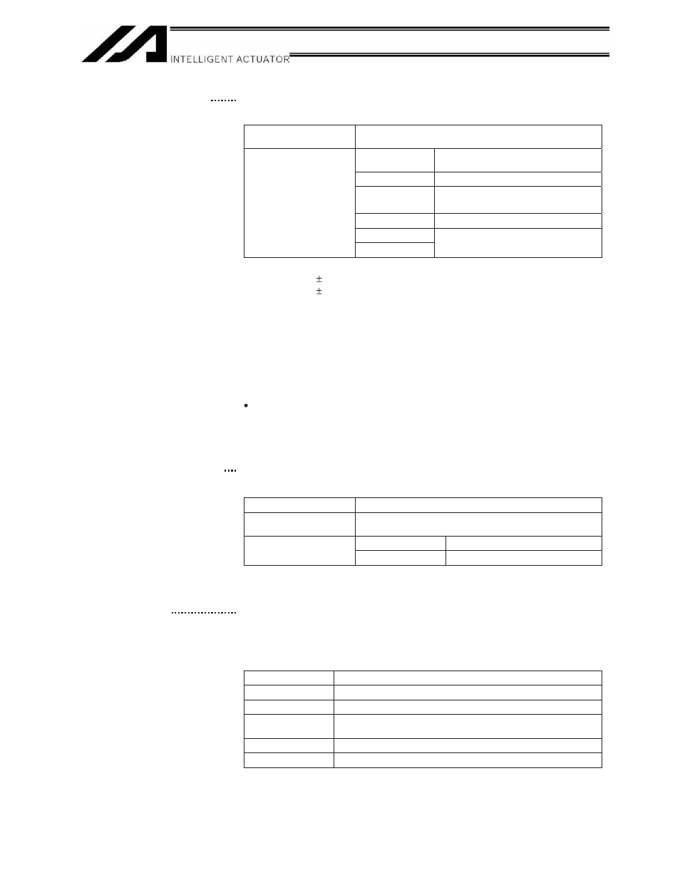
(12) System I/O connector
This connector is used to connect an emergency-stop switch, ENABLE
contact, ready relay, etc.
Connector
MC1.5/6-ST-3.5 by Phoenix Contact; 6-pin, 2-piece
connector
+24V OUT
+24-V power output for emergency
stop
EMG IN
Emergency-stop input
+24V OUT
+24-V power output for safety gate
ENB IN
Safety-gate input
RDY OUT
Terminal assignments
RDY OUT
Ready-status output contact
Current flowing between the emergency-stop contacts:
J type
30 mA
10%
K type
43 mA
10%
Between +24V OUT and EMG IN: Operation is permitted when a contact-
B emergency stop input is received or the line between the two
connectors is shorted. If the line becomes open, an emergency stop will
be actuated and the drive source will be cut off.
Between +24V OUT and ENB IN: Operation is permitted when a contact-
B safety gate input is received or the line between the two connectors is
shorted. If the line becomes open, the drive source will be cut off.
Between RDY OUTs: Contact-A is output under the conditions below.
SYSRDY is output (software = PIO trigger program can be run) and hardware is
normal (emergency stop is not being actuated and hardware error is not being
detected).
The lines between +24V OUT and EMG IN and between +24V OUT and
ENB IN have been shorted by cables before the shipment.
(13) I/O24V power connector
(general-purpose type
only)
This connector is used to externally supply I/O power to the isolated part
when DI and DOs are mounted in the I/O connectors explained in (18)
and (19). 24 V must be supplied externally.
Supported cable size
0.75 ~ 1.25 mm
2
(AWG16)
Connector
MC1.5/2-ST-3.5 by Phoenix Contact; 2-pin, 2-piece
connector
24V IN
+24-V power input for I/Os
Terminal assignments
0V
I/O GND
With a compact type, power is supplied externally to pin Nos. 1 and 50 of
the I/O connector in (18).
(14) Panel window
This window consists of a 4-digit, 7-segment LED display and five LED
lamps that indicate the status of the equipment.
For the information shown on the display, refer to 2, “Explanation of
Codes Displayed on the Panel Window” or the “Error Code Table.”
Meanings of Five LEDs
Name
Status when the LED is lit
RDY
CPU ready (program can be run)
ALM
CPU alarm (system-down level error), CPU hardware error
EMG
Emergency stop has been actuated, CPU hardware error,
power-system hardware error
PSE
Power-system hardware error
CLK
System clock error