Introduction, 1introduction, X-sel-j – IAI America XSEL-KE User Manual
Page 16
1
Introduction
Introduction
The controller models covered by this operation manual are as follows.
Model number
X-SEL-J
X-SEL-KE
For details on models, refer to the table below.
Model number
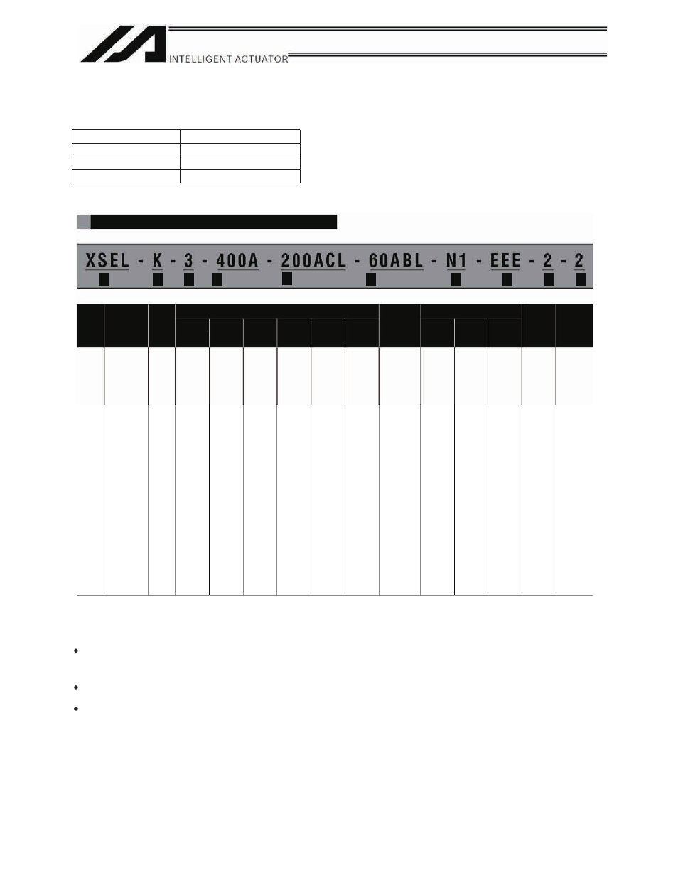
Model number example
Model number table
20
(20W)
30D
(30W for DS)
30R
(30W for RS)
60
(60W)
100
(100W)
150
(150W)
200
(200W)
300
(300W)
400
(400W)
600
(600W)
750
(750W)
[6] Expansion I/O slot
Slot 3
Slot 4
[7]
I/O flat
cable
length
[8]
Power-
supply
voltage
E
(Not used)
C
(CC-Link
connection
16/16 board)
N1
(Expansion PIO,
32 input/16
output
NPN board)
N2
(Expansion PIO,
16 input/32
output
NPN board)
N3
(Expansion PIO,
18 input/18
output
NPN board)
P1
(Expansion PIO,
32 input/16
output
PNP board)
P2
(Expansion PIO,
16 input/32
output
PNP board)
P3
(Multi-point I/O
PNP 48/48)
SA
(Expansion
SIO type A)
SB
(Expansion
SIO type B)
SC
(Expansion
SIO type C)
2: 2 m
(Standard)
3: 3 m
5: 5 m
0: None
(First axis)
[1]
[2]
[3]
[4]
[5]
(Second axis)
[6]
[7]
[8]
[4]
(Third axis)
[4]
[1]
Series
name
[2]
Controller
type
[3]
Number
of axes
[4] Details of axes 1 to 4
Motor
wattage
Encoder
type
Brake
Creep
sensor
Home
sensor
(LS)
Synchronization
specification
[5]
Standard
I/O
(Slot 1)
Slot 2
XSEL
J
(Compact type)
1
(1 axis)
2
(2 axis)
3
(3 axis)
4
(4 axis)
I
(Incremental)
A
(Absolute)
Blank
(Without
brake)
B
(With brake)
Blank
(Without creep
sensor)
C
(With creep
sensor)
Blank
(Without origin
sensor)
L
(With origin
sensor)
N1
(Expansion PIO,
32 input/16 output
NPN board)
N3
(Expansion PIO,
48 input/48 output
NPN board)
P1
(Expansion PIO,
32 input/16 output
PNP board)
P3
(Expansion PIO,
48 input/48 output
PNP board)
DV
(DeviceNet
256/256 board)
CC
CC-Link
256/256 board)
PR
ProfiBus
256/256 board
ET
(Ethernet data
communication
board)
E
(Not used)
C
(CC-Link
connection
16/16 board)
N1
(Expansion PIO,
32 input/16
output
NPN board)
N2
(Expansion PIO,
16 input/32
output
NPN board)
N3
(Expansion PIO,
18 input/18
output
NPN board)
P1
(Expansion PIO,
32 input/16
output
PNP board)
P2
(Expansion PIO,
16 input/32
output
PNP board)
P3
(Multi-point I/O
PNP 48/48)
SA
(Expansion
SIO type A)
SB
(Expansion
SIO type B)
SC
(Expansion
SIO type C)
1: Single-phase 100 V
2: Single-phase 200 V
Blank
(Without
synchronization)
M
(Master axis
specification)
S
(Slave axis
specification)
X-SEL-J
KE
(CE-compliant)
K
(General-
purpose type)
K
(General-
purpose type)
The X-SEL Controller is available with one to four axes. As with the conventional SEL Controller, it can be connected and
used with various actuators. When connecting actuators, always use dedicated cables.
After turning OFFthe main power, be sure to wait for at least 5 seconds before turning it ON.
Any shorter interval may generate “E88: Power system error (Other).”
Do not plug in/out the connectors while the power is still supplied to the controller. Doing so may result in malfunction.
Notes on installing the absolute-data backup battery (absolute specification)
Follow the steps below to install the battery in order to initialize the battery circuit and thereby prevent the battery from
being consumed early:
(1)
Connect the encoder cable.
(2)
Turn on the power.
(3)
Install the absolute-data backup battery.
Be sure to perform the above operation after the encoder cable is disconnected for relocation, etc.
Read the operation manual for each actuator. If you have purchased our optional PC software and/or teaching pendant,
read the respective operation manuals, as well.
Compact type
Purpose type
CE-compliant
Specification