IAI America PCON-CFA User Manual
Page 95
3. PCON-CA/CF
A
89
3.4.2 Monitor LED Indicators
The two LEDs, MS and NS, provided on the front panel of the controller are used to check the node (controller)
condition and network condition.
The LEDs illuminate in two colors (orange and green), and you can monitor the conditions listed in the table below
based on the illumination status and color of each LED.
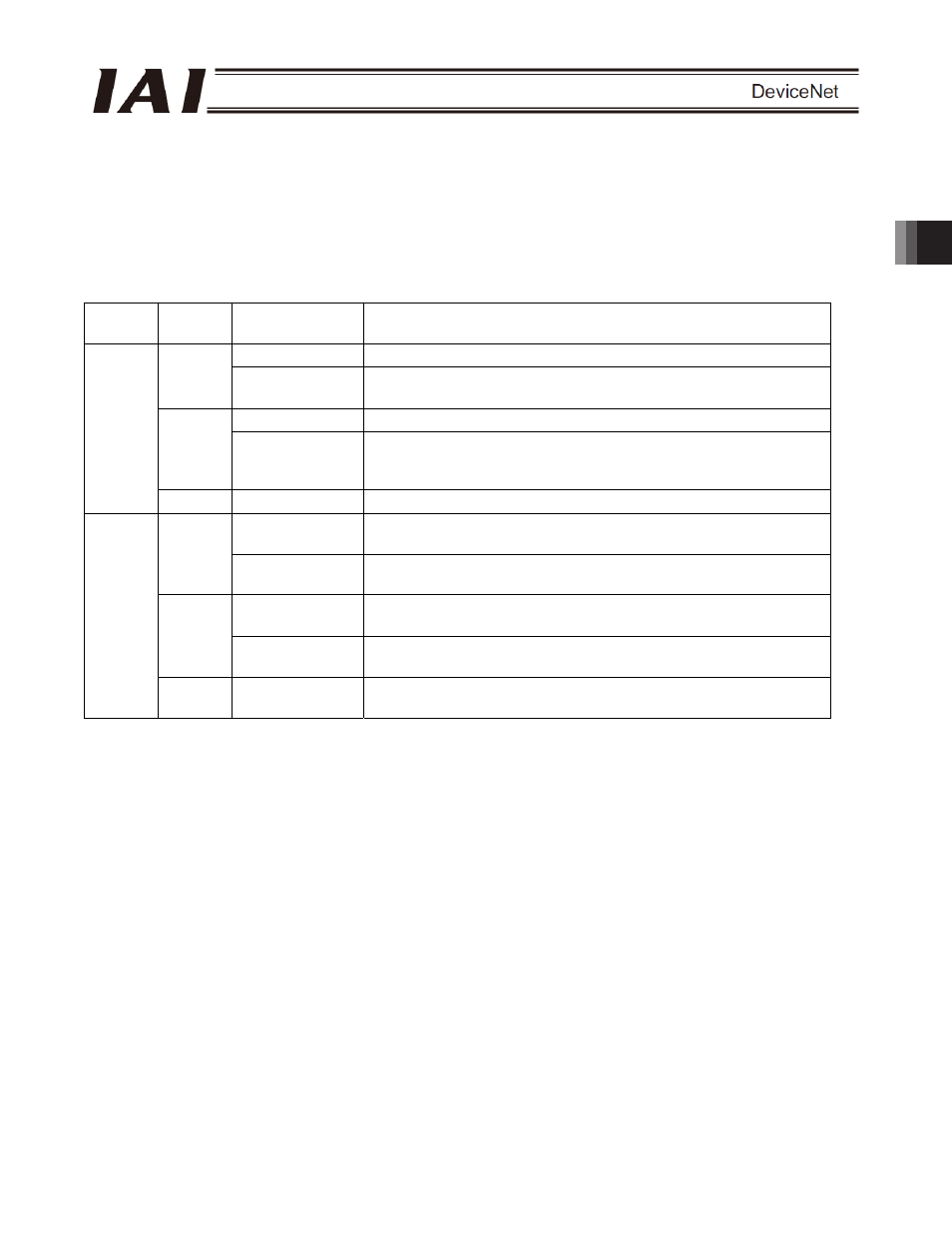
MS (Module Status) LED:
Condition of the node (controller)
NS (Network Status) LED: Condition of the network
{ Steady light, X : Off, ڏ : Blinking
LED Color
Illumination
status
Description (meaning)
{
The board is operating normally.
Green
ڏ
A hardware error occurred. The error may be reset by
reconnecting the power.
{
A hardware error occurred. The board must be replaced.
Orange
ڏ
A user setting error, configuration error or other minor error is
present. These errors can be reset by setting the applicable item
again, etc.
MS
-
X
DeviceNet is initializing or the power is not supplied.
{
Network connection has been established and the board is
communicating normally.
Green
ڏ
The board is online, but network connection is not yet established.
Communication is stopped. (The network is normal.)
{
Node address duplication or bus-off state was detected.
Communication is not possible.
Orange
ڏ
A communication error occurred (communication time-out
occurred).
NS
- X
The board is not online.
DeviceNet power is not supplied.
Self test is performed when the power is turned on.
During the test, the monitor LEDs cycle in the following sequence:
[1] NS turns off.
[2] MS illuminates in steady green (approx. 0.25 second).
[3] MS illuminates in steady orange (approx. 0.25 second).
[4] MS illuminates in steady green.
[5] NS illuminates in steady green (approx. 0.25 second).
[6] NS illuminates in steady orange (approx. 0.25 second).
[7] NS turns off.
When the self test is finished and the board starts communicating normally, both the MS and NS LEDs
change to steady green.