IAI America PCON-CFA User Manual
Page 31
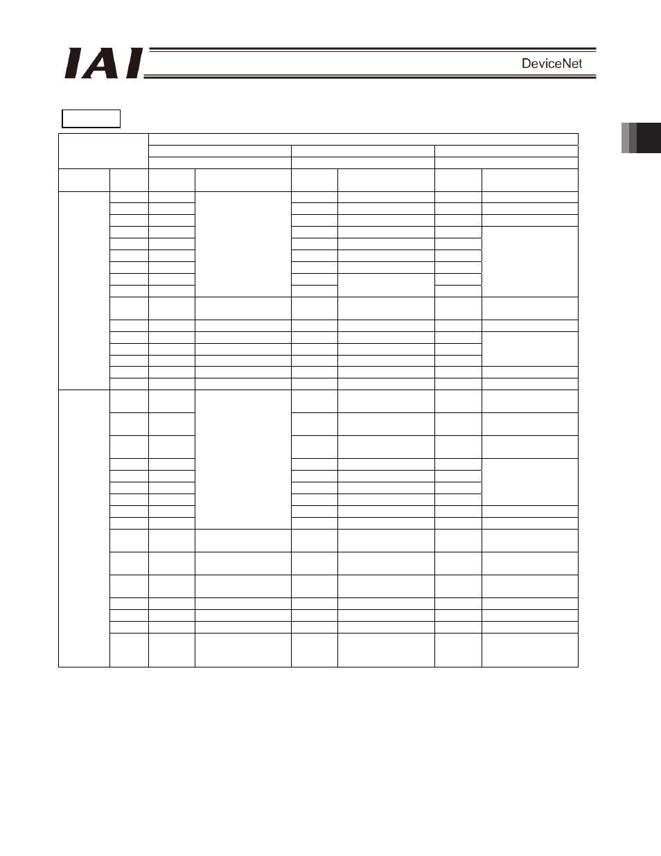
2. ACON-C/CG,
PCON-C/CG
25
Setting of Parameter No. 25
512-point mode
Solenoid mode 1
Solenoid mode 2
3 4 5
Category
Port
No.
Symbol
Signal name
Symbol
Signal name
Symbol
Signal name
0 PC1
ST0 Start
position
0 ST0 Start
position
0
1 PC2
ST1 Start
position
1 ST1 Start
position
1
2 PC4
ST2 Start
position
2 ST2 Start
position
2
3 PC8
ST3 Start
position
3 -
4 PC16
ST4 Start
position
4
-
5 PC32
ST5 Start
position
5
-
6 PC64
ST6 Start
position
6
-
7 PC128
-
-
8 PC256
Command position
number
-
Not available.
-
Not available.
9 BKRL
Forced brake
release
BKRT
Forced brake
release
BKRL
Forced brake
release
10 RMOD Operation
mode RMOD
Operation
mode RMOD Operation
mode
11
HOME
Home return
HOME
Home return
-
12 *STP
Pause
*STP
Pause
-
13
CSTR
Positioning start
-
Not available.
-
Not available.
14 RES
Reset
RES
Reset
RES
Reset
PLC
output
o
PCON
input
15
SON
Servo ON command
SON
Servo ON command
SON
Servo ON command
0
PM1
PE0
Position 0 complete
LS0
Rear end move
command 0
1
PM2
PE1
Position 1 complete
LS1
Rear end move
command 1
2
PM4
PE2
Position 2 complete
LS2
Rear end move
command 2
3
PM8
PE3
Position 3 complete
-
4
PM16
PE4
Position 4 complete
-
5
PM32
PE5
Position 5 complete
-
6
PM64
PE6
Position 6 complete
-
Not available.
7
PM128
ZONE1
Zone 1
ZONE1
Zone 1
8 PM256
Completed position
number
PZONE
Position zone
PZONE
Position zone
9 RMDS
Operation mode
status
RMDS
Operation mode
status
RMDS
Operation mode
status
10 HEND
Home return
complete
HEND
Home return
complete
HEND
Home return
complete
11 PEND
Position complete
signal
PEND
Position complete
signal
-
Position complete
signal
12 SV
Ready
SV
Ready
SV
Ready
13 *EMGS Emergency
stop *EMGS
Emergency stop
*EMGS
Emergency stop
14 *ALM
Alarm
*ALM
Alarm
*ALM
Alarm
PCON
output
o
PLC input
15
LOAD/
TRQS
Load output
judgment/torque
level
LOAD/
TRQS
Load output
judgment/torque
level
- Not
available.
The signals indicated by * are ON in a normal state.
The signals denoted by “Not available” are not controlled (their ON/OFF status is indeterminable).
PCON