IAI America PCON-CFA User Manual
Page 115
3. PCON-CA/CF
A
109
3.7.5 Full Direct Mode (Number of Occupied Channels: 16)
In this mode, the actuator is operated by specifying all values relating to positioning control (target position, speed,
etc.) directly from the PLC.
Set each value in the I/O area.
The key ROBO Cylinder functions that can be controlled in this mode are summarized in the table below.
ROBO Cylinder function
{: Direct control
X: Invalid
Home-return operation
{
Positioning operation
{
Speed and acceleration/deceleration setting
{
Pitch feed (inching)
{
Push-motion operation
{
Speed change during movement
{
Operation at different acceleration and deceleration
{
Pause
{
Zone signal output
{
PIO pattern selection
X
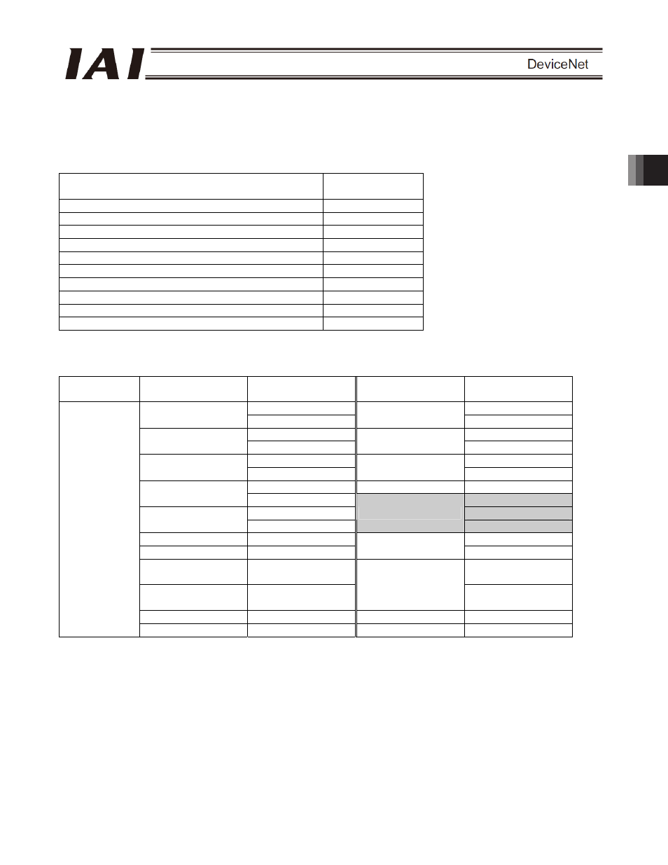
(1) PLC channel configuration (* n indicates the node address of each axis.)
Parameter No.
84
PCON-CA/CFA
input register
PLC output channel
PCON-CA/CFA
output register
PLC input channel
n+0 n+0
Target position
n+1
Current position
n+1
n+2 n+2
Positioning band
n+3
Command current
n+3
n+4 n+4
Speed
n+5
Current speed
n+5
n+6 Alarm
code n+6
Zone boundary+
n+7
n+7
n+8
n+8
Zone boundary-
n+9
Occupied area
n+9
Acceleration n+10
n+10
Deceleration n+11
Total moving count
n+11
Push-motion
current-limiting value
n+12 n+12
Load current
threshold
n+13
Total moving
distance
n+13
Control signal 1
n+14
Status signal 1
n+14
3
Control signal 2
n+15
Status signal 2
n+15
(Note) The areas denoted by “occupied area” cannot be used for any other purpose. Also exercise caution to
avoid node address duplication.