IAI America PCON-CFA User Manual
Page 176
4. SCON-CA
170
(1) PLC channel configuration (* n indicates the node address of each axis.)
Parameter No.
84
SCON-CA DI
(port number)
PLC output channel
SCON-CA DO
(port number)
PLC input channel
0 0~15 n+0 0~15 n+0
(Note) Exercise caution to avoid node address duplication.
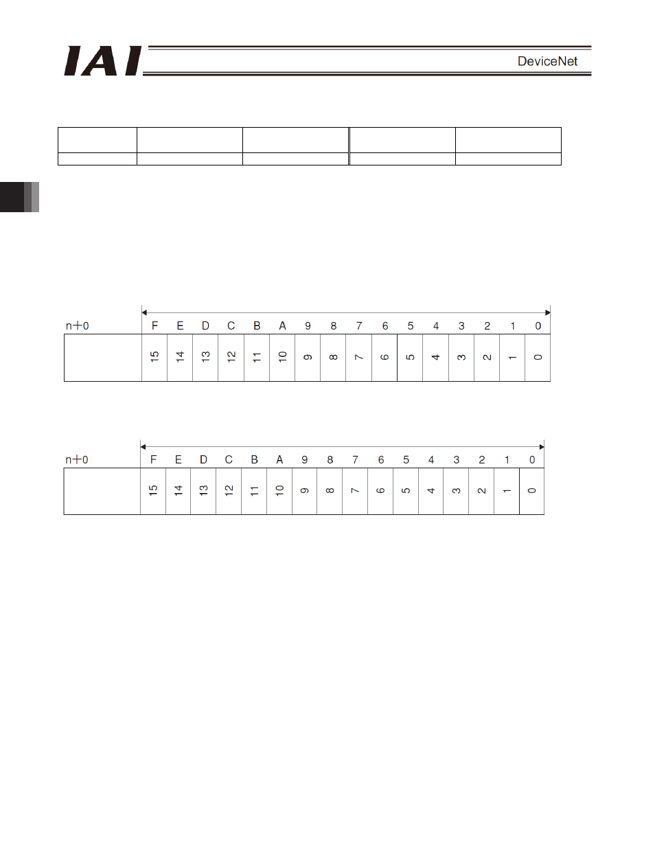
(2) I/O signal assignments for each axis
The I/O signals of each axis consist of one input word (channel) and one output word (channel) in the I/O areas.
z Each channel is controlled by ON/OFF bit signals.
PLC output
Channel (* n indicates the node address of each axis.)
PLC input
Channel (* n indicates the node address of each axis.)
1 word (channel) = 16 bits
Controller
output port
number
1 word (channel) = 16 bits
Controller
input port
number