IAI America PCON-CFA User Manual
Page 54
2. ACON-C/CG,
PCON-C/CG
48
(1) PLC channel configuration (* n indicates the node address of each axis.)
Parameter No.
84
ACON or PCON DI
and input register
PLC output channel
ACON or PCON DO
and output register
PLC input channel
Port number 0 to 15
n+0
Current position
n+0
n+1
Occupied area
n+1
n+2 n+2
n+3
Current position
n+3
n+4 n+4
4
Occupied area
n+5
Command current
n+5
(Note) The areas denoted by “occupied area” cannot be used for any other purpose. Also exercise caution to
avoid node address duplication.
(2) I/O signal assignments for each axis
The I/O signals of each axis consist of six input words (channels) and six output words (channels) in the I/O
areas.
z The channels controlled by port number are controlled using ON/OFF bit signals.
z The current position is a 2-word (32-bit) binary data (unit: 0.01 mm).
z The command current is a 2-word (32-bit) binary data (unit: 1 mA).
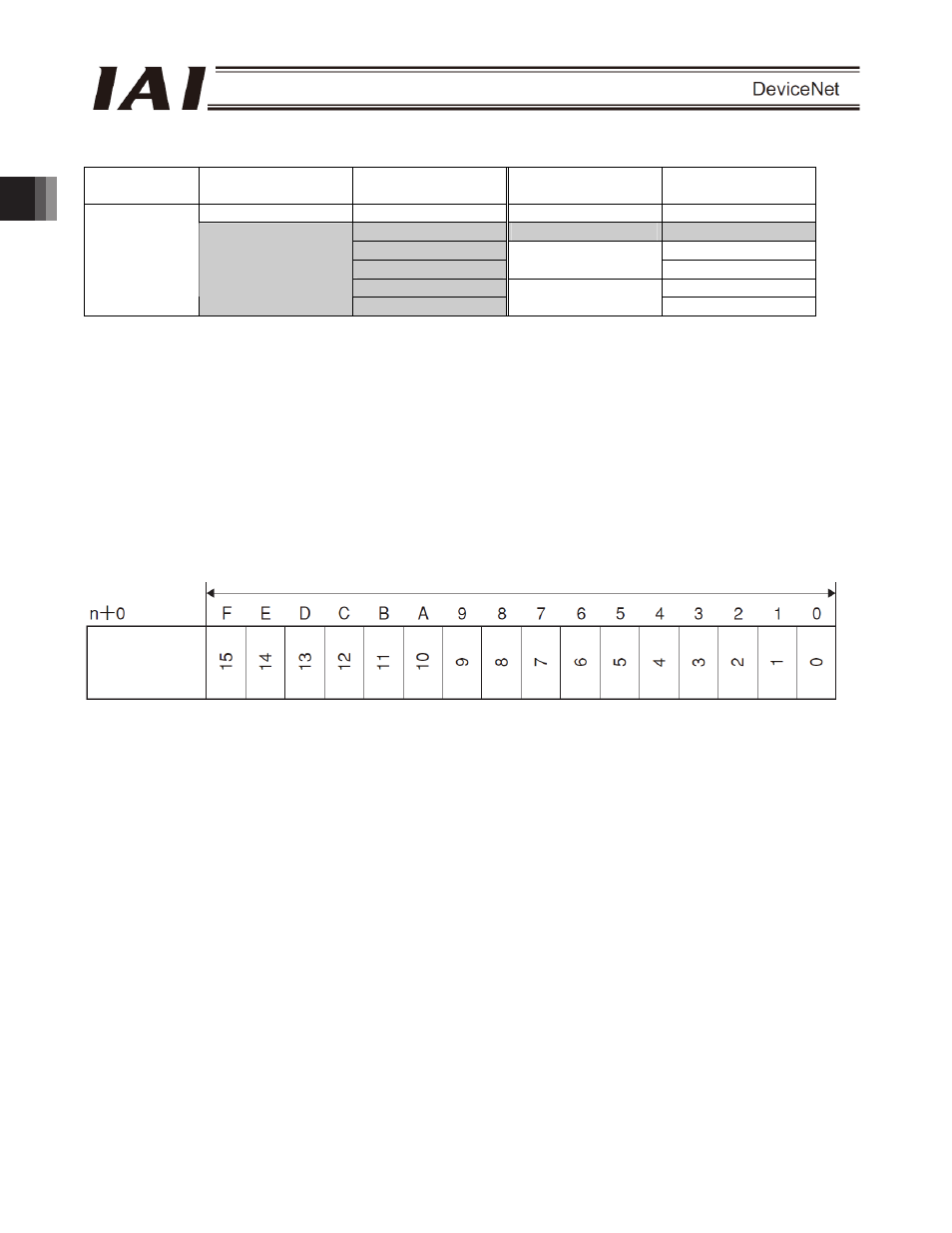
PLC output (* n indicates the node address of each axis.)
Channel
1 word (channel) = 16 bits
Controller
input port
number