IAI America PCON-CFA User Manual
Page 219
4. SCON-CA
213
4.7.9 Remote I/O Mode 3 (Number of Occupied Channels: 6)
In this mode, the actuator is operated by means of force control (push-motion operation based on feedback of
load cell values) and also by specifying position numbers in the same manner you would using PIOs (24-V I/Os).
Set position data using the RC PC software or other teaching tool.
The number of available positions is determined by the setting of parameter No. 25, “PIO pattern.”
In this mode, all functions in the remote I/O mode are available, plus additional functions to read the current
position and force feedback data.
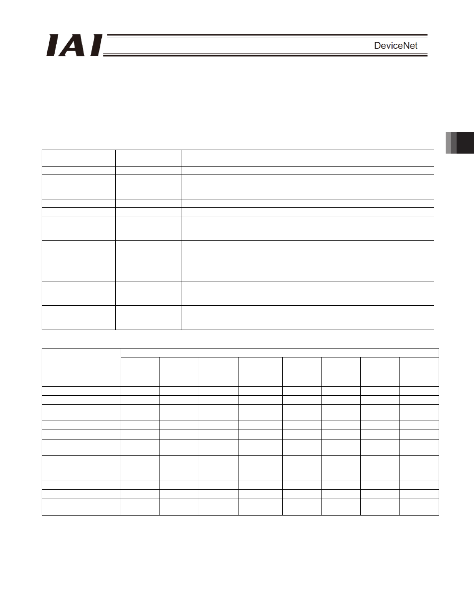
The features of each PIO pattern are shown below. (For details, refer to the operation manual for the controller.)
Value set in
parameter No. 25
Operation mode
I/O specification
0
Positioning mode
64 positioning points and two zone output points are available.
1
Teaching mode
64 positioning points and one zone output point is available.
Positioning operation and jog operation are supported.
The current position can be written to a specified position.
2
256-point mode
256 positioning points and one zone output point is available.
3
512-point mode
512 positioning points are available. There are no zone outputs.
4
Solenoid mode 1
7 positioning points and two zone output points are available.
A direct operation command can be issued for each position number.
A position complete signal is output for each position number.
5
Solenoid mode 2
3 positioning points and two zone output points are available.
The actuator is operated by specifying forward, backward and intermediate
position commands.
A position complete signal is output separately for the front end, rear end and
intermediate position.
6 Force
control
mode
1 (a dedicated load
cell is used)
32 positioning points, 1 zone output
7 Force
control
mode
2 (a dedicated load
cell is used)
5 positioning points, 1 zone output
A direct operation command can be issued for each position number.
A position complete signal is output for each position number.
The key ROBO Cylinder functions that can be controlled in this mode are summarized in the table below.
PIO pattern
ROBO Cylinder function
0:
Positioning
mode
1:
Teaching
mode
2:
256-point
mode
3:
512-point
mode
4:
Solenoid
valve mode
1
5:
Solenoid
valve mode
2
6.
Force
control
mode 1
7.
Force
control
mode 2
Home return operation
{
{
{
{
{
X
{
{
Positioning operation
{
{
{
{
{
{
{
{
Speed & acceleration/
deceleration setting
{
{
{
{
{
{
{
{
Pitch feed (inching)
{
{
{
{
{
{
{
{
Push-motion operation
{
{
{
{
{
X
{
{
Speed change during
movement
{
{
{
{
X
{
{
X
Operation at different
acceleration and
deceleration
{
{
{
{
{
{
{
{
Pause
{
{
{
{
{
{ (*1)
{
{
Zone signal output
{
{
{
X
{
{
{
{
PIO pattern selection
(set by parameter)
{
{
{
{
{
{
{
{
{: Supported / X: Not supported
(*1) This function is supported when parameter No. 27, “Move command type” is set to “0.”
The actuator can be paused by turning the move command OFF.