IAI America PCON-CFA User Manual
Page 210
4. SCON-CA
204
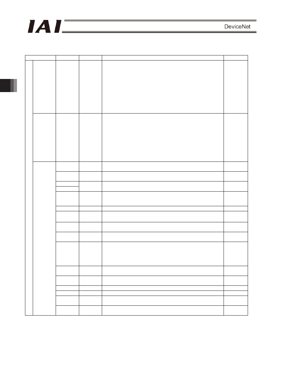
(3) I/O signal assignments
(* In the table, ON indicates that the applicable bit is “1,” while OFF indicates that the bit is “0.”)
Signal type
Bits
Symbol
Description
Details
Target
position
32-bit data
-
32-bit signed integer.
Specify the target position as a position in the absolute
coordinate system.
The setting unit is 0.01 mm and the allowable specification range
is -999999 to 999999.
(Example) To set “+25.40 mm,” specify “2540.”
If the entered value exceeds the range between the soft limits
(0.2 mm inside the limits) set by the parameters, the movement
will be limited to the soft limit (0.2 mm inside the limit).
* If target positions are entered as hexadecimals, enter negative
values using 2’s complements.
4.9 (1)
Specified
position
number
16-bit data
PC1 ~
PC512
16-bit integer.
To operate the actuator, you must set position data associated
with predefined operating conditions using the PC software or
teaching pendant.
Use one of these registers to specify the position number for
which the desired data has been input.
The allowable specification range is 0 to 767.
If the specified value is outside the above range or corresponds
to a position not yet set, an alarm will occur when the start signal
is turned ON.
4.9 (1)
b15 BKRL
Forced brake release: The brake is released when this signal
turns ON.
4.7.11 (18)
b14 RMOD
Operation mode: The AUTO mode is selected when this signal is
OFF, and the MANU mode is selected when the signal is ON.
4.7.11 (19)
b13
b12
- Not
available.
-
b11 -
Position/simple-direct switching: The position mode is selected
when this signal is OFF, and the simple direct mode is selected
when the signal is ON.
4.7.11 (20)
b10 -
Not
available.
-
b9 CLBR
Load cell calibration command: Calibration is performed
when this signal turns ON.
4.7.11 (32)
b8 JOG+
+Jog: The actuator moves in the direction opposite home when
this signal is ON.
4.7.11 (13)
b7 JOG-
-Jog: The actuator moves in the direction of home when this
signal is ON.
4.7.11 (13)
b6 JVEL
Jog-speed/inch-distance switching: The values set in parameter
No. 26, “Jog speed” and parameter No. 48, “Inch distance” are
used when this signal is OFF, and the values set in parameter
No. 47, “Jog speed 2” and parameter No. 49, “Inch distance 2”
are used when the signal is ON.
4.7.11 (14)
b5 JISL
Jog/inch switching: Jog operation is performed when this signal
is OFF, and inch operation is performed when the signal is ON.
4.7.11 (15)
b4 SON
Servo ON command: The servo turns ON when this signal turns
ON.
4.7.11 (5)
b3
RES
Reset: A reset is performed when this signal turns ON.
4.7.11 (4)
b2
STP
Pause: A pause command is issued when this signal turns ON.
4.7.11 (11)
b1 HOME
Home return: A home-return command is issued when this signal
turns ON.
4.7.11 (6)
PLC output
Control
signal
b0 CSTR
Positioning start: A move command is issued when this signal
turns ON.
4.7.11 (7)