IAI America PCON-CFA User Manual
Page 25
2. ACON-C/CG,
PCON-C/CG
19
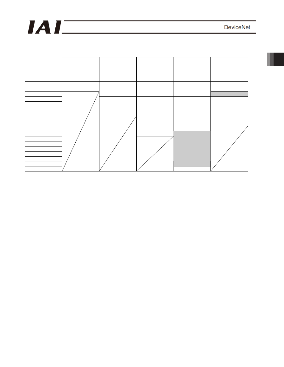
x ACON or PCON output o PLC input side (* n indicates the node address of each axis.)
ACON or PCON DO and output data register
Remote I/O mode
Position/simple
direct mode
Half direct mode
Full direct mode
Remote I/O mode
2
PLC input area
(channel)
Number of
occupied
channels: 1CH
Number of
occupied
channels: 4CH
Number of
occupied
channels: 8CH
Number of
occupied
channels: 16CH
Number of
occupied
channels: 6CH
n
Port number 0 to
15
Port number 0 to
15
n+1
Current position
Current position
Current position
Occupied area
n+2
n+3
Completed
position number
(simple alarm ID)
n+4 Status
signal
Command current Command current
Current position
n+5
n+6
Current speed
Current speed Command
current
n+7
Alarm code
Alarm code
n+8 Status
signal
n+9
n+10
n+11
n+12
n+13
n+14
Occupied area
n+15
Status signal
(Note) The areas denoted by “occupied area” are occupied according to the operation mode setting.
These areas cannot be used for any other purpose. Also exercise caution to avoid node address
duplication.