7 communicating with the master station – IAI America PCON-CFA User Manual
Page 171
4. SCON-CA
165
4.7
Communicating with the Master Station
4.7.1 Operation Modes and Corresponding PLC I/O Areas
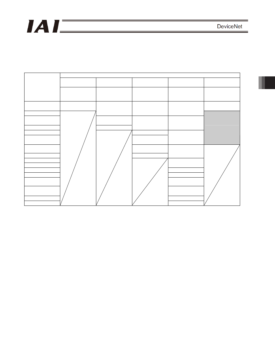
The channel assignments in each mode are shown below.
x PLC
output
o SCON-CA input (* n indicates the node address of each axis.)
SCON-CA DI and input data register
Remote I/O mode
Position/simple
direct mode
Half direct mode
Full direct mode
Remote I/O mode
2
PLC output area
(channel)
Number of
occupied
channels: 1CH
Number of
occupied
channels: 4CH
Number of
occupied
channels: 8CH
Number of
occupied
channels: 16CH
Number of
occupied
channels: 6CH
n
Port number 0 to
15
Port number 0 to
15
n+1
Target position
Target position
Target position
n+2
Specified position
number
n+3 Control
signal
Positioning band
Positioning band
n+4 Speed
n+5
Acceleration/
deceleration
Speed
specification
Occupied area
n+6
Push-motion
current-limiting value
n+7 Control
signal
Zone boundary+
n+8
n+9
Zone boundary-
n+10 Acceleration
n+11 Deceleration
n+12
Push-motion
current-limiting value
n+13
Load current
threshold
n+14 Control
signal
1
n+15
Control signal 2
(Note) The areas denoted by “occupied area” are occupied according to the operation mode setting.
These areas cannot be used for any other purpose. Also exercise caution to avoid node address
duplication.