IAI America PCON-CFA User Manual
Page 185
4. SCON-CA
179
4.7.4 Half Direct Mode (Number of Occupied Channels: 8)
In this mode, the target position, positioning band, speed, acceleration/deceleration and push-motion current are
specified directly and numerically from the PLC.
Set each value in the I/O areas. To use the zone function, set appropriate values in parameter Nos. 1, 2, 23 and
24.
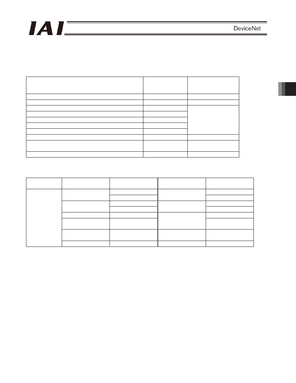
The key ROBO Cylinder functions that can be controlled in this mode are summarized in the table below.
Actuator function
{: Direct control
U: Indirect control
X: Invalid
Remarks
Home-return operation
{
Positioning operation
{
Speed and acceleration/deceleration setting
{
Pitch feed (inching)
{
Push-motion operation
{
Speed change during movement
{
Operation at different acceleration and deceleration
X
Pause
{
Zone signal output
U
Parameters must be
set
PIO pattern selection
X
(1) PLC channel configuration (* n indicates the node address of each axis.)
Parameter No.
84
SCON-CA input
register
PLC output channel
SCON-CA output
register
PLC input channel
n+0 n+0
Target position
n+1
Current position
n+1
n+2 n+2
Positioning band
n+3
Command current
n+3
Speed n+4
n+4
Acceleration/
deceleration
n+5
Current speed
n+5
Push-motion
current-limiting value
n+6 Alarm
code n+6
2
Control signal
n+7
Status signal
n+7
(Note) Exercise caution to avoid node address duplication.