IAI America PCON-CFA User Manual
Page 47
2. ACON-C/CG,
PCON-C/CG
41
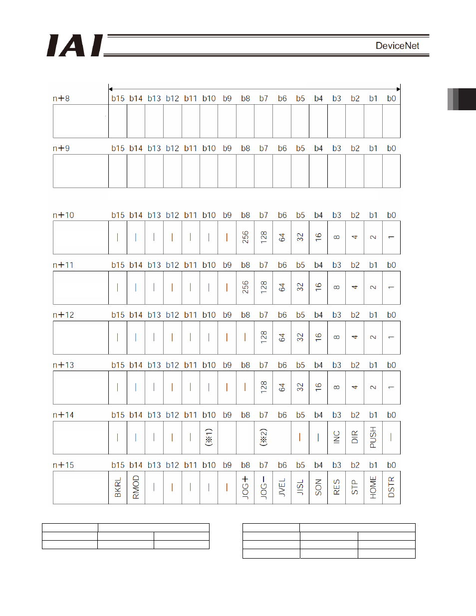
Channel (* n indicates the node address of each axis.)
(*1) Signal assignment for b10 of n+14
(*2) Signal assignments for b7 and b6 of n+14
Symbol
Symbol
Controller ACON PCON
Controller ACON
PCON
b10 -
SMOD
b7
MOD1 -
b6
MOD0
-
(*3) This is a dedicated function for PCON controllers. It is not available with ACON controllers.
1 word (channel) = 16 bits
Zone
boundary-
(lower word)
Zone
boundary-
(upper word)
If the zone boundary is a negative value, it is indicated by a 2’s complement.
Acceleration
Deceleration
Push-motion
current-limiting
value
Load current
threshold (*3)
Control signal
1
Control signal
2
ASO0
ASO1