Description of the data path, Block diagrams of the cameras, Black and white cameras – ALLIED Vision Technologies Pike F-1600 User Manual
Page 134: Vised chapter, Chapter, Figure 68: block diagram b/w camera, Pike technical manual v5.1.2
Description of the data path
PIKE Technical Manual V5.1.2
134
Description of the data path
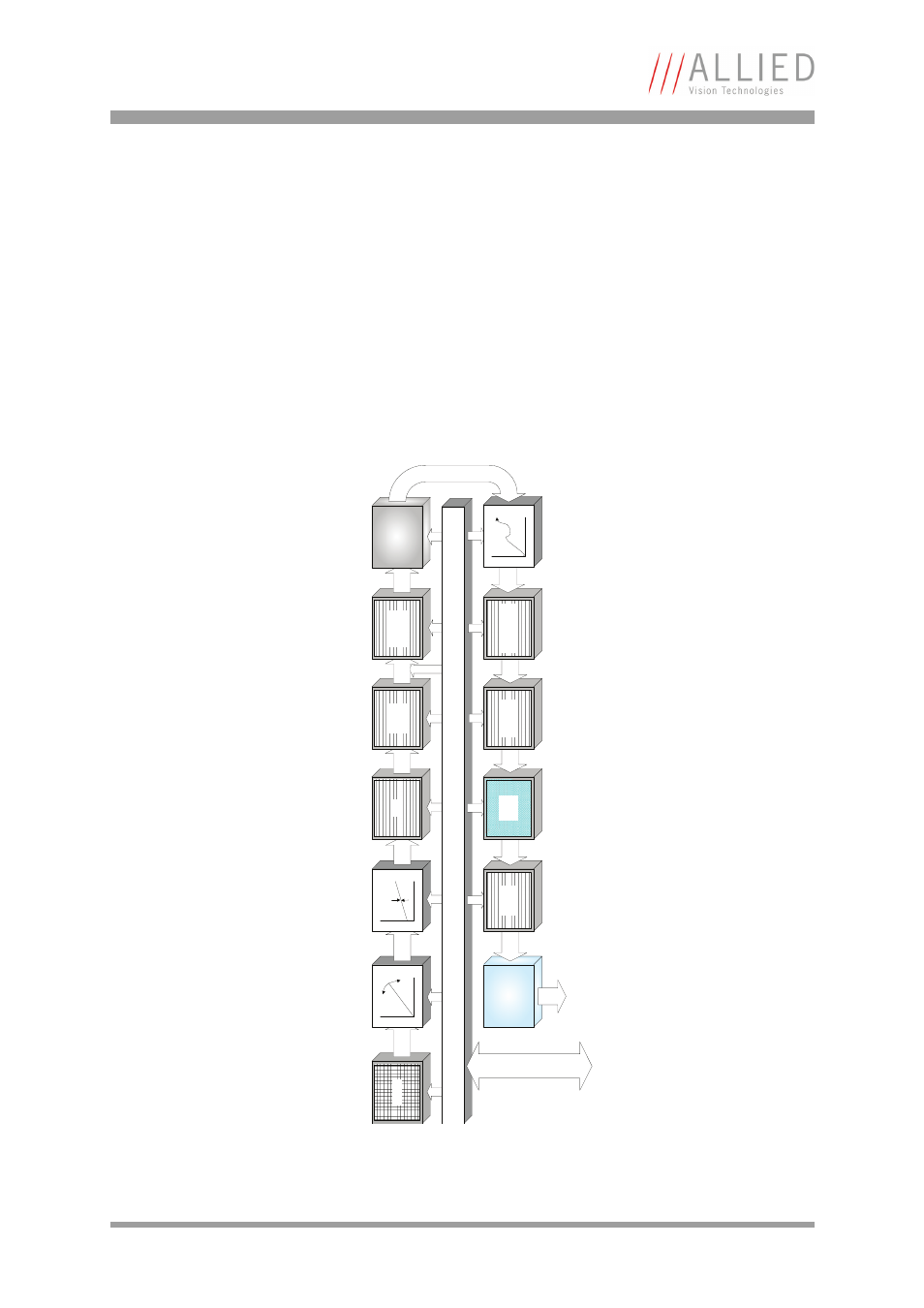
Block diagrams of the cameras
The following diagrams illustrate the data flow and the bit resolution of image
data after being read from the CCD sensor chip in the camera. The individual
blocks are described in more detail in the following paragraphs. For sensor data
see Chapter
Black and white cameras
Figure 68: Block diagram b/w camera
S
e
ns
or
Ana
log
Gain
Ana
log
Offset
Ana
log
AD
C
14 bit
Channel
balance
Test-Pattern
IEEE 1394b
interface
1394b
14 bit
Horizontal
mirror
14 bit
Shading
correction
Camera control
HIROSE I/O
RS232
8 B
it
Frame
memory
16
bit
HS
NR
control
14
bi
t
Horizontal
masking
14
bit
Horizontal
sub-sampling
14 bit
LUT
14 bit
This manual is related to the following products: