Sample program, 2 instructions – Omron SYSMAC CP CP1E-N@@D@-@ User Manual
Page 179
2-143
2 Instructions
CP1E CPU Unit Instructions Reference Manual(W483)
Data Sh
ift I
n
stru
ctio
ns
2
NASL/NSLL
Sample program
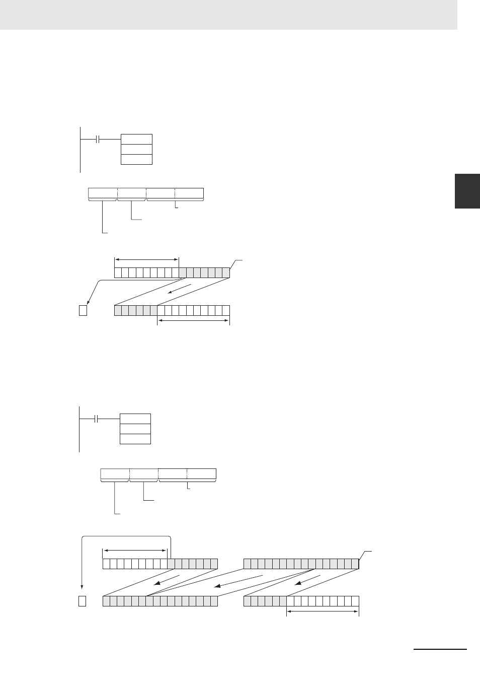
When CIO 0.00 is ON, The contents of CIO 100 is shifted 10 bits to the left (from the rightmost bit to the
leftmost bit). The number of bits to shift is specified in bits 0 to 7 of word W0 (control data). The con-
tents of bit 0 of CIO 100 is copied into bits from which data was shifted and the contents of the right-
most bit which was shifted out of range is shifted into the Carry Flag (CY). All other data is lost.
When CIO 0.00 is ON, CIO 100 and CIO 101 will be shifted to the left (from the rightmost bit to the left-
most bit) by 10 bits. The number of bits to shift is specified in bits 0 to 7 of W0 (control data). The con-
tents of bit 0 of CIO 100 is copied into bits from which data was shifted and the contents of the
rightmost bit which was shifted out of range is shifted into the Carry Flag (CY). All other data is lost.
NASL
100
W0
D
C
0.00
C
0
8
11
8
12
15
0
7
4 3
0
A
No. of bits to shift: 10 bits (0A Hex)
Always 0.
Data shifted into register
8 Hex: Contents of right-most bit shifted in
0
15
100
5
8 7 6
0
15 14 13 12
10
11
4 3
9 8
2 1
100
1 1 1 1 1 1 1 1
1
1
CY
1
1 0 0 1 0 0 1
0 0 1 0 0 1
Rightmost bit
Lost
No. of bits to shift: 10 bits
(Contents of the rightmost
bit is inserted.)
NSLL
100
W0
0.00
D
C
C
0
8
11
8
12
15
0
7
4 3
0
A
No. of bits to shift: 10 bits (0A Hex)
Always 0.
Data shifted into register
8 Hex: Contents of right-most bit shifted in
0
15
101
1
1
0 0 1 0 0 1
0 0 1 0 0 1
8 7
0
15
8 7 6 5
0
15
9 8 7
101
1 0 0 1 0 0 1 0
1
0
CY
1
100
1 0 0 1 0 0 1
0 0 1 0 0 1
0
15
10
7
9 8
100
1 1 1 1 1 1 1 1
1
1
1 0 0 1 0 0 1 0 0
Rightmost bit a
Lost
No. of bits to shift: 10 bits
(Contents of the rightmost
bit is shifted in)