Function, Hint precautions, 2 instructions – Omron SYSMAC CP CP1E-N@@D@-@ User Manual
Page 117
2-81
2 Instructions
CP1E CPU Unit Instructions Reference Manual(W483)
Tim
er and
Cou
nter
I
n
stru
ctio
ns
2
CNT/CNTX
Function
• The setting range 0 to 9,999 for CNT and 0 to 65,535 for CNTX(546).
Hint
Precautions
• Counter numbers are shared by the CNT, CNTX(546), CNTR(012) and CNTRX(548) instructions. If
two counters share the same counter number but are not used simultaneously, a duplication error will
be generated when the program is checked but the counters will operate normally. Counters which
share the same counter number will not operate properly if they are used simultaneously.
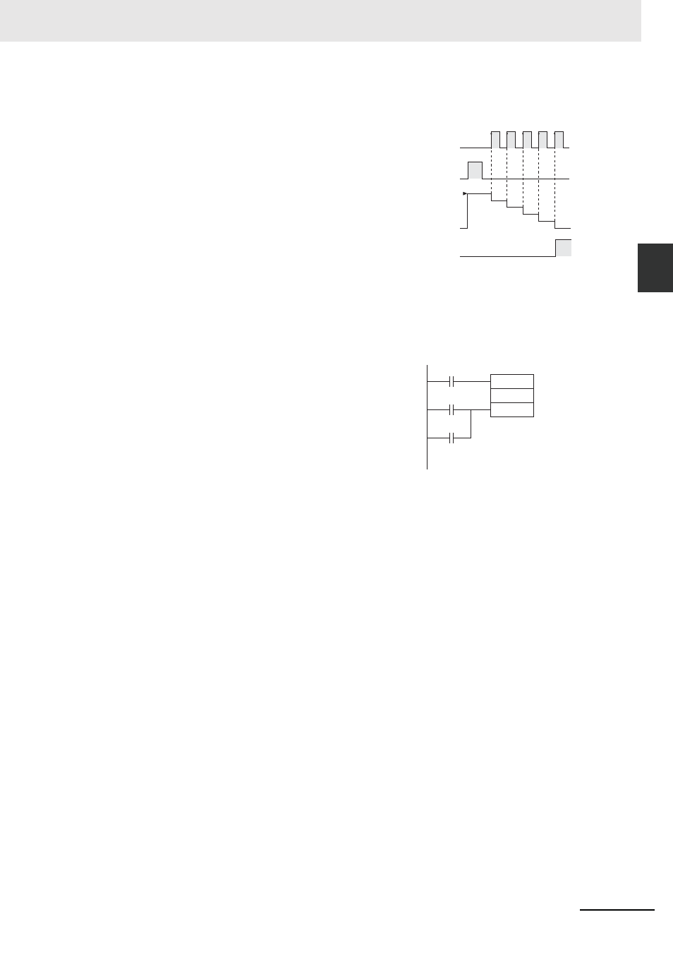
• A counter’s PV is refreshed when the count input goes from OFF to ON and the Completion Flag is
refreshed each time that CNT/CNTX(546) is executed. The Completion Flag is turned ON if the PV is
0 and it is turned OFF if the PV is not 0.
• The counter PV is decremented by 1 every
time that the count input goes from OFF to
ON. The Completion Flag is turned ON
when the PV reaches 0.
• Once the Completion Flag is turned ON,
reset the counter by turning the reset input
ON or by using the CNR(545)/CNRX(547)
instruction. Otherwise, the counter cannot
be restarted.
• The counter is reset and the count input is
ignored when the reset input is ON. (When
a counter is reset, its PV is reset to the SV
and the Completion Flag is turned OFF.)
• Counter PVs are retained even through a
power interruption. If you want to restart
counting from the SV instead of resuming
the count from the retained PV, add the
First Cycle Flag (A200.11) as a reset input
to the counter.
Note 1 In case CP1E CPU Unit is backed up in the capacitor and power remained OFF for a period in excess of
the following, the Counters PVs and Countup Flags are unfixed.
E-type CPU Unit
9 hours (60°C), 50 hours (25°C)
N/NA-type CPU Unit
7 hours (60°C), 40 hours (25°C)
2 By setting “Zero Clear Holding Memory” for the PLC Setup, the Counters PVs and Countup Flags will be
cleared each time power turns ON. In this case, the DM area (D) and Holding Area (H) will be cleared at
the same time.
3 N/NA-type CP1E CPU Unit (CP1E-N/NA
D - ) can be equipped with a battery. With the battery
installed, the Counters PVs and Countup Flags can be retained during power OFF.
ON
OFF
ON
OFF
ON
OFF
0
SV
Count input
Counter PV
Reset input
Completion
Flag
CNT
N
S
First Cycle Flag
(A200.11)