Monitoring at startup, Monitor displays – Yaskawa G5HHP Drive User Manual
Page 86
Setting User Constants
4.2.4 Operation Mode
4 - 18
Const
Name
Output Signal Levels for
Valid Access Levels
Func-
tion
Const
ant
No.
Digital Operator
Display
Function
Output Signal Levels for
Multi-function Analog Out-
puts
Min.
Units
V/f
V/f w/
PG
Open
-loop
Vec-
tor
Flux
Vec-
tor
U3-01
Most recent fault
Information on the last fault
Q
Q
Q
Q
U3-01
Last Fault
Information on the last fault.
--
Q
Q
Q
Q
U3-02
Second most re-
cent fault
Information on the 2
nd
to last
fault
--
Q
Q
Q
Q
U3 02
Fault Message 2
fault.
--
Q
Q
Q
Q
U3-03
Third most recent
fault
Information on the 3
rd
to last
fault
--
Q
Q
Q
Q
U3 03
Fault Message 3
fault.
--
Q
Q
Q
Q
U3-04
Fourth/oldest fault
Information on the 4
th
to last
Q
Q
Q
Q
Fault
U3-04
Fault Message 4
Information on the 4 to last
fault.
--
Q
Q
Q
Q
Fault
histo-
ry
(See
U3-05
Cumulative opera-
tion time at fault
Elapsed running or power-on time
when the last fault occurred
Can’t be output.
1 hr
Q
Q
Q
Q
y
(See
note.)
U3 05
Elapsed Time 1
when the last fault occurred.
1 hr
Q
Q
Q
Q
note.)
U3-06
Accumulated time
of second fault
Elapsed running or power-on time
when the 2
nd
to last fault oc-
1 hr
Q
Q
Q
Q
U3 06
Elapsed Time 2
when the 2 to last fault oc
curred.
1 hr
Q
Q
Q
Q
U3-07
Accumulated time
of third fault
Elapsed running or power-on time
when the 3
rd
to last fault oc-
1 hr
Q
Q
Q
Q
U3 07
Elapsed Time 3
when the 3 to last fault oc
curred.
1 hr
Q
Q
Q
Q
U3-08
Accumulated time
of fourth/oldest
fault
Elapsed running or power-on time
when the 4
th
to last fault occurred.
1 hr
Q
Q
Q
Q
Elapsed Time 4
when the 4 to last fault occurred.
Note Faults CPF00, 01, 02, 03, UV1 and UV2 are not recorded in the fault history.
J
Monitoring at Startup
In operation mode, the frequency reference, output frequency, output current, and output voltage can be
monitored immediately if the factory presets are being used. One of these four values, the output voltage,
can be changed to a different monitor item. When an item other than the output voltage is to be monitored,
set that value in user constant o1-01 (Monitor selection). Refer to the example procedure given later in this
manual.
When the power is turned ON, the frequency reference will appear in the Unit’s data display if the factor
presets are being used. Any one of the four values monitored at startup (frequency reference, output frequen-
cy, output current, or the value set in user constant o1-01) can be selected to appear when the power is turned
ON.
The value that appears at startup is determined by user constant o1-02 (Monitor selection after power up).
User constants o1-01 and o1-02 can be changed in the Basic or Advanced access levels. These user constants
can be changed during operation.
J
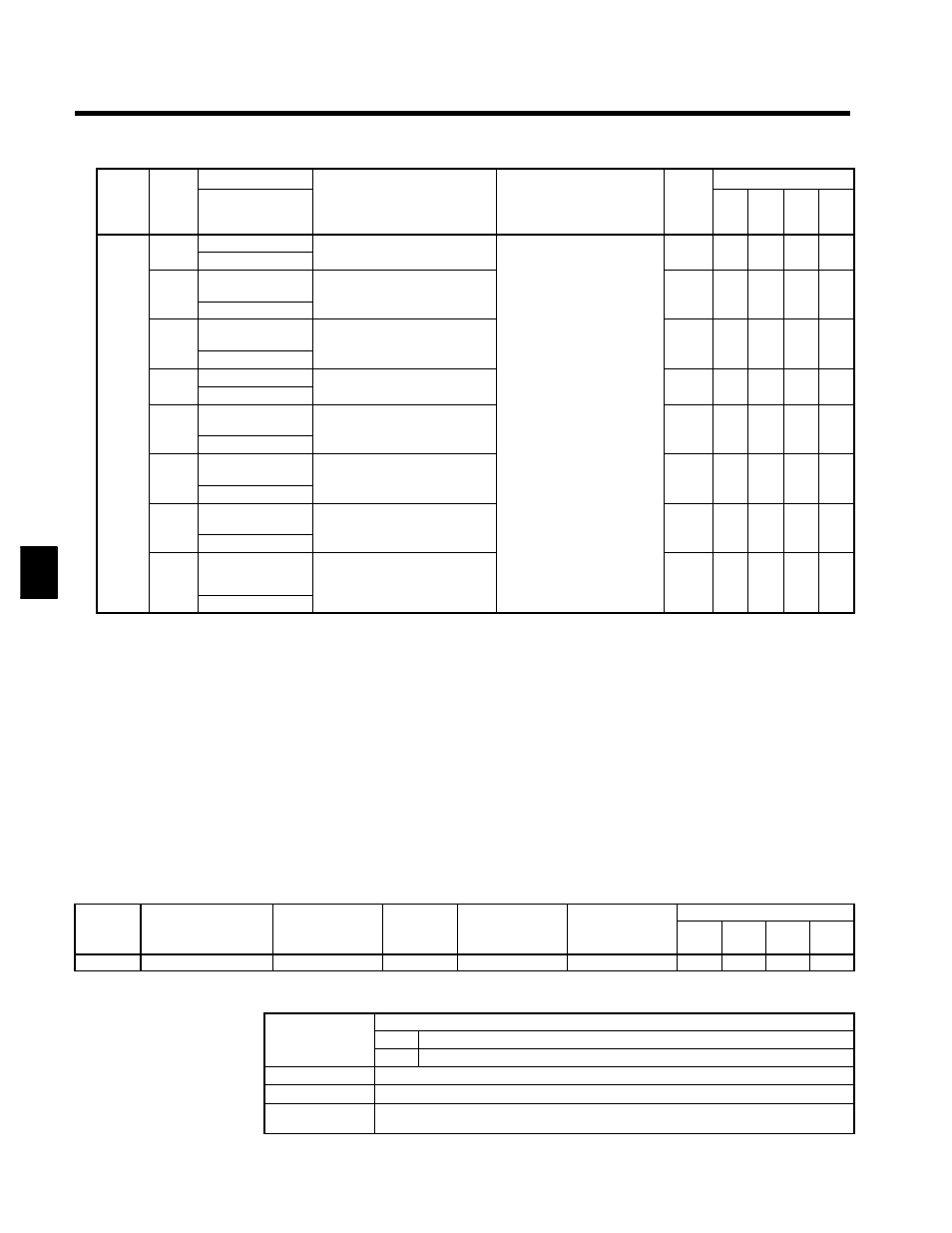
Monitor Displays
The following notation is used in this manual when describing user constants.
User
Change during
Setting
Valid Access Levels
User
Constant
Number
Display Name
Change during
Operation
Setting
Range
Unit
Factory Setting
V/f
Control
V/f with
PG
Open
Loop
Vector
Flux
Vector
o1-01
Monitor selection
f
4 to 28
--
6
B
B
B
B
Use the last two digits from the U1 Monitor list (U1-09) to select a value. For example, the torque reference
is U1-09, so input 9 to select the torque reference.
Change during
Indicates whether or not the constant can be changed during operation.
Change during
Operation
f
Can be changed during operation.
Operation
X
Cannot be changed during operation.
Setting Range
The setting range for the constant.
Units
The unit used to set the constant (“--” indicates that no unit is used).
Factory Setting
The value preset at the factory. (There are different factory settings for each control method,
i.e., if the control method is changed, the factory setting can also change.)
4