Setting a user-defined v/f pattern: e1-03 = “f – Yaskawa G5HHP Drive User Manual
Page 142
Basic Operation
6.3.2 V/f Pattern Selection: E1-03
6 - 24
J
Setting a User-defined V/f Pattern: E1-03 = “F”
D
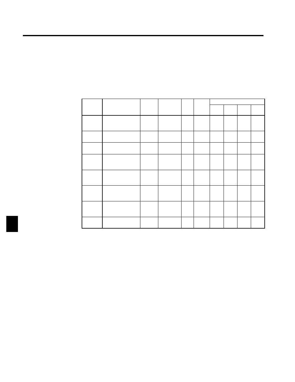
Constants E1-04 through E1-10 can be set by the user when E1-03 has been set to “F.” These constants
are read-only when E1-03 isn’t set to “F.”
D
When making the V/f characteristics a straight line, set the same value in E1-07 (middle output frequen-
cy) and E1-09 (minimum output frequency). In this case, constant E1-08 (middle output frequency volt-
age) will be disregarded.
D
The user constant numbers for motor 2 are given in parentheses.
Settings for E1-04 to E1-10 (E4-01 to E4-07) and E1-13
User
Change
during
Setting
Factory
Valid Access Levels
User
Constant
Number
Name
g
during
Opera-
tion
Setting
Range
Unit Factory
Setting
V/f
Control
V/f with
PG
Open
Loop
Vector
Flux
Vector
E1-04
(E4-01)
Max. output frequen-
cy
(FMAX)
x
50.0 to
150.0
Hz
60.0
Q
Q
Q
Q
E1-05
(E4-02)
Max. voltage
(VMAX)
x
0.0 to 510.0
*1
VAC 400.0
*1
Q
Q
Q
Q
E1-06
(E4-03)
Base frequency
(FA)
x
0.0 to 150.0
Hz
60.0
Q
Q
Q
Q
E1-07
(E4-04)
Mid. output frequen-
cy
(FB)
x
0.0 to 150.0
Hz
3.0
*2
Q
Q
A
X
E1-08
(E4-05)
Mid. output frequen-
cy voltage
(VC)
x
0.0 to 510.0
*1
VAC
24.0
*1,
*
2
Q
Q
A
X
E1-09
(E4-06)
Min. output frequen-
cy
(FMIN)
x
0.0 to 150.0
Hz
1.5
*2
Q
Q
Q
A
E1-10
(E4-07)
Min. output frequen-
cy voltage
(VMIN)
x
0.0 to 510.0
*1
VAC
12.0
*1, *2
Q
Q
A
X
E1-13
Base voltage
(VBASE)
x
0.0 to 510.0 VAC
0.0
*3
A
A
Q
Q
* 1. These values are for 400-VClass Inverters; multiply the values by approx. 1.5 for 575-VClass
Inverters.
* 2. The factory setting depends on the Inverter capacity. The factory settings shown in the table
are for 400-V Class, 200 to 800 kW Inverters. (See page 8 - 41.)
Refer to the graphs for “Setting: 1” on page 6 - 23.
* 3. If E1-13 is set to 0.0, E1-13 will be set to the same value as E1-05 following autotuning and
does not need to be set.
D
The factory settings for E1-07 through E1-10 will be set according to the control method whenever the
control method is changed. The factory settings shown in the table are for V/f control. See page 8 - 41.)
D
The four frequency settings must satisfy the following formula:
E1-04 (F
MAX
) ≥ E1-06 (F
A
) > E1-07 (F
B
) ≥ E1-09 (F
MIN
)
6