Motor 2 setup: e5 – Yaskawa G5HHP Drive User Manual
Page 288
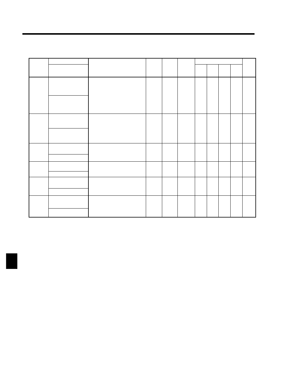
User Constants
8.2.4 Motor Constant Constants: E
8 - 22
J
Motor 2 Setup: E5
C
t t
Name
S tti
F t
Change
Control Methods
Constant
Number
Display
Description
Setting
Range
Factory
Setting
Change
during
Opera-
tion
V/f
V/f
with
PG
Open
Loop
Vector
Flux
Vector
Page
E5-01
Motor 2 rated current
Sets the motor rated current in 1 A
units.
;
These set values will become the
reference values for motor
protection torque limits and
37.0 to
740.0
370.0
x
A
x
A
x
7 8
E5-01
Motor 2 rated FLA
protection, torque limits and
torque control.
These values will automatically
be set if they were set during au-
totuning.
740.0
*2
370.0
*1
x
A
x
A
x
7 - 8
E5-02
Motor 2 rated slip
Sets the motor rated slip in Hz
units.
;
These set values will become the
f
l
f
li
0.00 to
1.30
x
A
x
A
x
7 8
E5-02
Motor 2 Slip Freq
;
reference values for slip com-
pensation.
These values will be automati-
cally set during autotuning.
0.00 to
20.00
1.30
*1
x
A
x
A
x
7 - 8
E5-03
Motor 2 no-load cur-
rent
Sets the motor no-load current in 1
A units.
;
Th
l
ill b
t
ti l
0.00 to
2000 0
96.0
*1
x
A
x
A
x
7 - 8
E5 03
Motor 2 No-load 1
;
These values will be automatical-
ly set during autotuning.
2000.0
*1
x
A
x
A
x
7 - 8
E5-04
Motor 2 number of
poles
Sets the number of motor poles.
;
These values will automatically
2 to 48
4
x
x
x
x
x
---
E5 04
Motor 2 # Poles
;
These values will automatically
be set during autotuning.
2 to 48
4
x
x
x
x
x
---
E5-05
Motor 2 line-to-line
resistance
Sets the motor phase-to-phase re-
sistance in Ω units.
;
Th
l
ill b
t
ti l
0.000 to
65 000
0.020
*1
x
A
x
A
x
7 - 8
E5 05
Motor 2 term Ohms
;
These values will be automatical-
ly set during autotuning.
65.000
*1
x
A
x
A
x
7 - 8
E5-06
Motor 2 leak induc-
tance
Sets the voltage drop due to motor
leakage inductance as a percentage
of the motor rated voltage.
0.0 to
30 0
5.0
*1
x
x
x
A
x
7 - 9
E5 06
Motor 2 Leak
g
;
These values will be automatical-
ly set during autotuning.
30.0
*1
x
x
x
A
x
7 - 9
* 1. The factory setting depends upon the Inverter capacity. The values for a 400-V class Inverter of 200 kW will be displayed. See
page 8 - 42.
* 2. The setting range is 10% to 200% of the Inverter’s rated output current. The values for a 400-V class Inverter of 200 kW will
be displayed.
8