4 motor constant constants: e, V/f pattern: e1 – Yaskawa G5HHP Drive User Manual
Page 285
8.2 Programming Mode Constants
8 - 19
8.2.4 Motor Constant Constants: E
J
V/f Pattern: E1
Consta
Name
S tti
F t
Change
Control Methods
Consta
nt
Num-
ber
Display
Description
Setting
Range
Factory
Setting
Change
during
Opera-
tion
V/f
V/f
with
PG
Open
Loop
Vector
Flux
Vector
Page
E1-01
Input voltage
setting
Sets the Inverter input voltage in units of 1 V.
;
This setting is used as the reference value
f f
ti
h
th
t ti
f
360 to
460
400
*1
x
Q
Q
Q
Q
6 - 18
6 - 21
6 31
E1 01
Input Voltage
;
g
for functions such as the protection func-
tions.
460
*1
*1
x
Q
Q
Q
Q
6 - 31
6 - 39
Motor selection
0: Standard fan-cooled motor (general-pur-
pose motor)
1: Standard blower-cooled motor (Inverter-
6 - 21
E1-02
Motor Selec-
tion
1: Standard blower-cooled motor (Inverter-
exclusive motor)
;
This setting is used as the reference value
for functions such as the protection func-
tions.
0, 1
0
x
Q
Q
Q
Q
6 - 21
6 - 39
E1-03
V/f pattern
selection
0 to E: Select from the 15 preset patterns.
F: Custom user-set patterns (Applicable for
0 to F
F
x
Q
Q
x
x
6 - 22
E1 03
V/F Selection
F: Custom user-set patterns (Applicable for
settings E1-04 to E1-10.)
0 to F
F
x
Q
Q
x
x
6 - 22
E1-04
Max. output
frequency
50.0 to
60 0
x
Q
Q
Q
Q
6 24
E1-04
Max Frequen-
cy
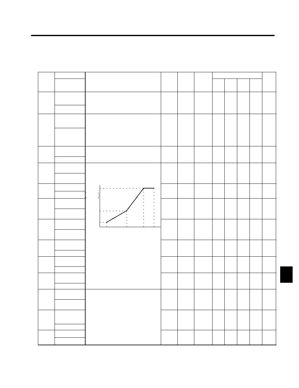
Output voltage (V)
50.0 to
150.0
60.0
x
Q
Q
Q
Q
6 - 24
E1-05
Max. voltage
Output voltage (V)
VMAX
E1-05
0.0 to
510.0
400.0
x
Q
Q
Q
Q
6 24
E1-05
Max Voltage
E1-05
V BASE
E1-13
510.0
*1
400.0
*1
x
Q
Q
Q
Q
6 - 24
E1-06
Base frequen-
cy
E1-13
VC
0.0 to
60 0
x
Q
Q
Q
Q
6 24
E1-06
Base Frequen-
cy
VC
E1-08
Fre-
0.0 to
150.0
60.0
x
Q
Q
Q
Q
6 - 24
E1-07
Mid. output fre-
quency
VMIN
E1-10
FMIN
FB
FA
FMAX
Fre-
quency
(Hz)
0.0 to
3.0
x
Q
Q
A
x
6 24
E1-07
Mid Frequency
A
FMIN
E1-09
FB
E1-07
FA
E1-06
FMAX
E1-04
0.0 to
150.0
3.0
*2
x
Q
Q
A
x
6 - 24
E1-08
Mid. output fre-
quency voltage
;
To set V/f characteristics in a straight line,
set the same values for E1-07 and E1-09.
In this case the setting for E1-08 will be
0.0 to
510.0
22.0
*1
x
Q
Q
A
x
6 - 24
E1 08
Mid Voltage A
In this case, the setting for E1-08 will be
disregarded.
Al
th t th f
f
i
5 0.0
*1
*2
x
Q
Q
A
x
6 - 24
E1-09
Min. output fre-
quency
g
Always ensure that the four frequencies
are set in the following manner:
E1-04 (FMAX) ≧ E1-06 (FA) > E1-07
0.0 to
150 0
0.5
*2
x
Q
Q
Q
A
6 - 24
E1 09
Min Frequency
E1-04 (FMAX) ≧ E1-06 (FA) > E1-07
(FB) ≧ E1-09 (FMIN)
150.0
*2
x
Q
Q
Q
A
6 - 24
E1-10
Min. output fre-
quency voltage
(
)
(
)
0.0 to
510.0
4.0
*1
x
Q
Q
A
x
6 - 24
E1 10
Min Voltage
510.0
*1
*2
x
Q
Q
A
x
6 - 24
E1-11
Mid. output fre-
quency 2
0.0 to
0.0
x
A
A
A
A
E1-11
Mid Frequency
B
0.0 to
150.0
0.0
*3
x
A
A
A
A
----
E1-12
Mid. output fre-
quency voltage
2
Set only to fine-adjust V/f for the output
range when using flux vector control.
Normally, this setting is not required.
0.0 to
510.0
*1
0.0
*3
x
A
A
A
A
----
Mid Voltage B
Normally, this setting is not required.
*1
3
E1-13
Base voltage
0.0 to
510.0
0.0
x
A
A
Q
Q
6 24
E1-13
Base Voltage
510.0
*1
0.0
*4
x
A
A
Q
Q
6 - 24
8