Torque detection: l6, Torque limit: l7 – Yaskawa G5HHP Drive User Manual
Page 303
8.2 Programming Mode Constants
8 - 37
J
Torque Detection: L6
C
t t
Name
S tti
F t
Change
Control Methods
Constant
Number
Display
Description
Setting
Range
Factory
Setting
Change
during
Opera-
tion
V/f
V/f
with
PG
Open
Loop
Vector
Flux
Vector
Page
L6-01
Torque detection
selection 1
0: Overtorque detection disabled.
1: Detection during speed agree
only/Operation continues after
detection (Minor fault)
2: Detection during run/Operation
continues after detection (Minor
fault)
0 to 4
0
x
B
B
B
B
7 - 95
L6 01
Torq Det 1 Sel
fault)
3: Detection during speed agree
only/Inverter output is shut off
after detection (Fault)
4: Detection during run/Inverter
output is shut off after detection
(Fault)
0 to 4
0
x
B
B
B
B
7 - 95
L6-02
Torque detection level
1
Vector control: Motor rated torque
is set as 100%.
V/f control In rt r r t d c rr nt is
0 to 300
150
x
B
B
B
B
7 - 95
L6 02
Torq Det 1 Lvl
V/f control: Inverter rated current is
set as 100%.
0 to 300
150
x
B
B
B
B
7 - 95
L6-03
Torque detection time
1
Sets the torque detection time in
1-second units
0.0 to
10 0
0.1
x
B
B
B
B
7 - 95
L6 03
Torq Det 1 Time
1-second units.
10.0
0.1
x
B
B
B
B
7 - 95
L6-04
Torque detection
selection 2
Setting procedure is the same as for
“Torque detection selection 1”
0 to 4
0
x
A
A
A
A
7 - 95
L6 04
Torq Det 2 Sel
“Torque detection selection 1”
(L6-01 to L6-03.)
0 to 4
0
x
A
A
A
A
7 - 95
L6-05
Torque detection level
2
(
)
The following outputs are possible:
Torque detection selection 1:
Multi function output “Torque
0 to 300
150
x
A
A
A
A
7 - 95
L6 05
Torq Det 2 Lvl
Multi-function output “Torque
detection selection 1” NO/NC
0 to 300
150
x
A
A
A
A
7 - 95
L6-06
Torque detection time
2
detection selection 1 NO/NC
Torque detection selection 2:
Multi-function output “Torque
detection selection 2” NO/NC
0.0 to
10 0
0.1
x
A
A
A
A
7 - 95
L6 06
Torq Det 2 Time
detection selection 2” NO/NC
10.0
0.1
x
A
A
A
A
7 95
J
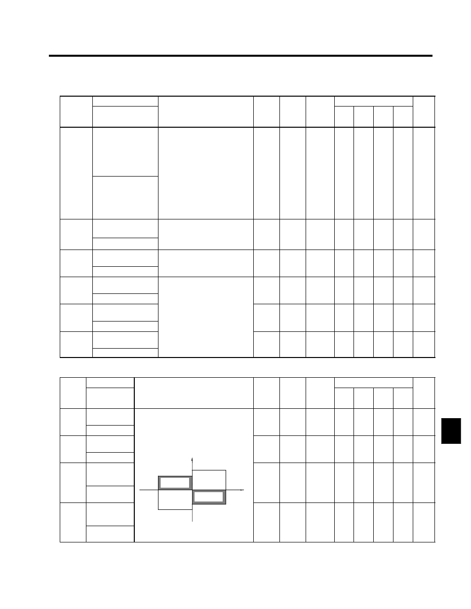
Torque Limit: L7
Consta
Name
S tti
F t
Change
Control Modes
Consta
nt
Num-
ber
Display
Description
Setting
Range
Factory
Setting
Change
during
Opera-
tion
V/f
V/f
with
PG
Open
Loop
Vector
Flux
Vector
Page
L7-01
Forward torque
limit
0 to 300
200
x
x
x
B
B
7 - 4
7 28
L7 01
Torq Limit Fwd
Sets the torque limit value as a percentage
f h
d
0 to 300
200
x
x
x
B
B
7 - 28
L7-02
Reverse torque
limit
Sets the torque limit value as a percentage
of the motor rated torque.
Four individual regions can be set.
Output torque
0 to 300
200
x
x
x
B
B
7 - 4
7 28
L7 02
Torq Limit Rev
Output torque
Forward side
0 to 300
200
x
x
x
B
B
7 - 28
L7-03
Forward regen-
erative torque
limit
Forward side
L7-01
L7-04
Motor
speed
Regenera-
tive state
0 to 300
200
x
x
x
B
B
7 - 4
7 28
L7 03
Torq Lmt Fwd
Rgn
Reverse
w
ard
speed
tive state
Regenera-
tive state
0 to 300
200
x
x
x
B
B
7 - 28
L7-04
Reverse re-
generative
torque limit
L7-02
Reverse side
L7-03
Fo
rw
tive state
0 to 300
200
x
x
x
B
B
7 - 4
7 28
L7 04
Torq Lmt Rev
Rgn
0 to 300
200
x
x
x
B
B
7 - 28
8