Yaskawa G5HHP Drive User Manual
Page 210
Advanced Operation
7.5.1 Application Constants: b
7 - 46
PID Control Settings
D
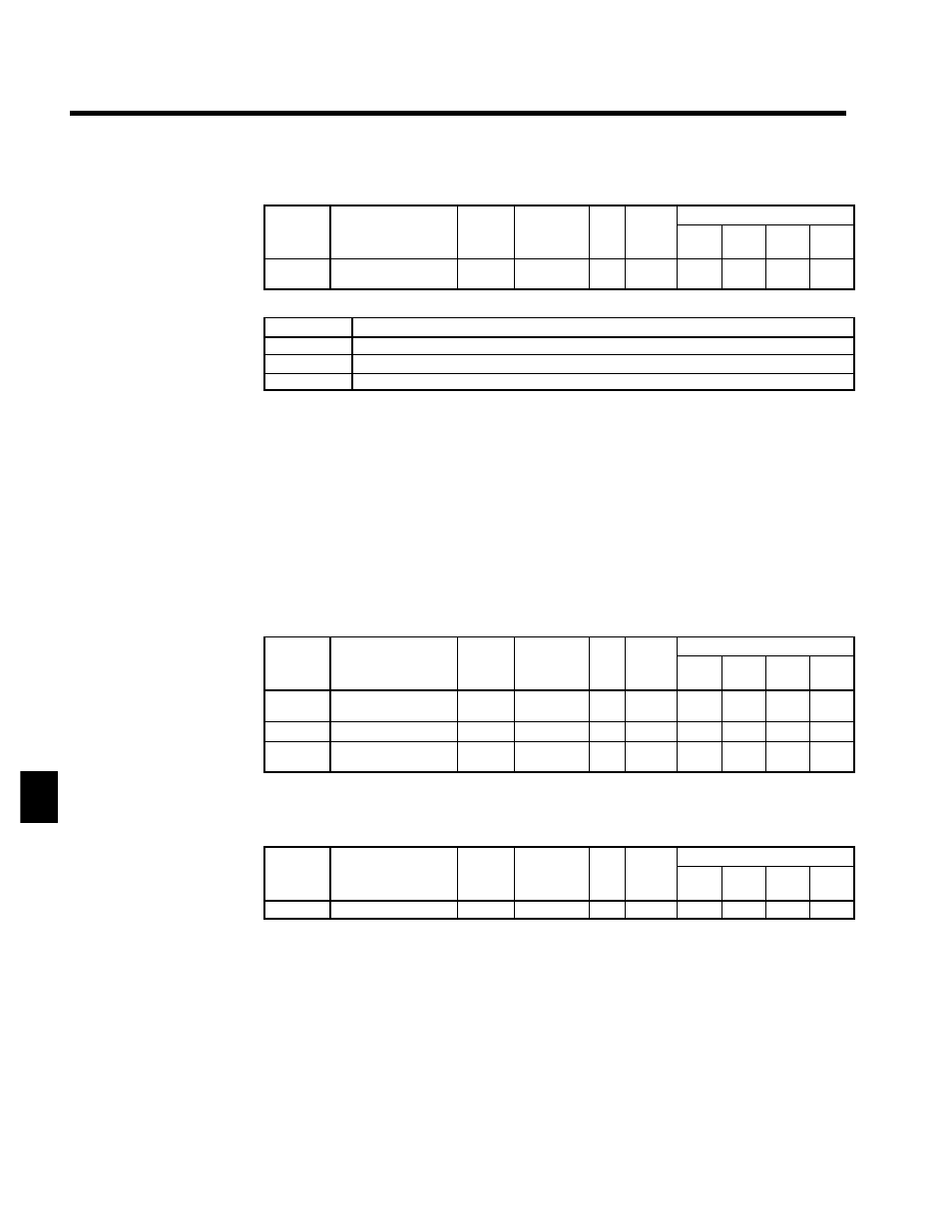
PID Control Mode Selection: b5-01
User
Change
during
Setting
Factory
Valid Access Levels
User
Constant
Number
Name
g
during
Opera-
tion
Setting
Range
Unit Factory
Setting
V/f
Control
V/f with
PG
Open
Loop
Vector
Flux
Vector
b5-01
PID control mode
selection
x
0 to 2
--
0
A
A
A
A
D
Settings
Setting
Contents
0
PID control disabled
1
PID control enabled, deviation signal is subject to derivative control.
2
PID control enabled, feedback signal is subject to derivative control.
•
To enable PID control, set either “1” or “2.” (Normally “2” is used, for measured-value derivative
PID control).
•
When PID control is enabled, the target value input is determined by constant b1-01 (reference
selection).
•
When target value input is set to b1--01=0 (digital operator), setting value becomes o1--03 (% unit),
and the target value should be input by percent. (When switching speed reference, 100% becomes
the max. frequency reference value.)
•
The feedback value is input from a multi-function analog input terminal or frequency reference (cur-
rent) terminal. Set PID feedback (setting: B) for either the constant H3-05 (multi-function analog
input, terminal 42), or constant H3-09 (multi-function analog input, terminal 39) function selection.
(See Table 7.11.) Adjust the amount of feedback by setting the gain and bias of the analog inputs
that are used.
D
Proportional gain (P), Integral (I) Time, and Differential (D) Time: b5-02, b5-03, b5-05
•
Adjust the responsiveness of the PID control by means of the proportional gain (P), integral time
(I), and derivative time (D).
User
Change
during
Setting
Factory
Valid Access Levels
User
Constant
Number
Name
g
during
Opera-
tion
Setting
Range
Unit Factory
Setting
V/f
Control
V/f with
PG
Open
Loop
Vector
Flux
Vector
b5-02
Proportional gain (P)
f
0.00 to
25.00
Mul-
tiple
1.00
A
A
A
A
b5-03
Integral (I) time
f
0.0 to 360.0
s
1.0
A
A
A
A
b5-05
Differential (D) time
f
0.00 to
10.00
s
0.00
A
A
A
A
•
Optimize the responsiveness by adjusting it while operating an actual load (mechanical system).
(Refer to Adjusting PID Control on page 7 - 47.) Any control (P, I, or D) that is set to zero (0.0, 0.00)
will not operate.
D
Integral (I) Limit: b5-04
User
Change
during
Setting
Factory
Valid Access Levels
User
Constant
Number
Name
g
during
Opera-
tion
Setting
Range
Unit Factory
Setting
V/f
Control
V/f with
PG
Open
Loop
Vector
Flux
Vector
b5-04
Integral (I) limit
f
0.0 to 100.0
%
100.0
A
A
A
A
•
This constant prevents the calculated value of the integral control in the PID control from exceeding
the fixed amount.
•
There is normally no need to change the setting.
•
Reduce the setting if there is a risk of load damage, or of the motor going out of step, by the Inverter’s
response when the load suddenly changes. If the setting is reduced too much, the target value and
the feedback value will not match.
•
Set this constant as a percentage of the maximum output frequency, with the maximum frequency
taken as 100%.
D
PID Limit: b5-06
7